176 Chapter 4
Assembly Replacement
Front Frame
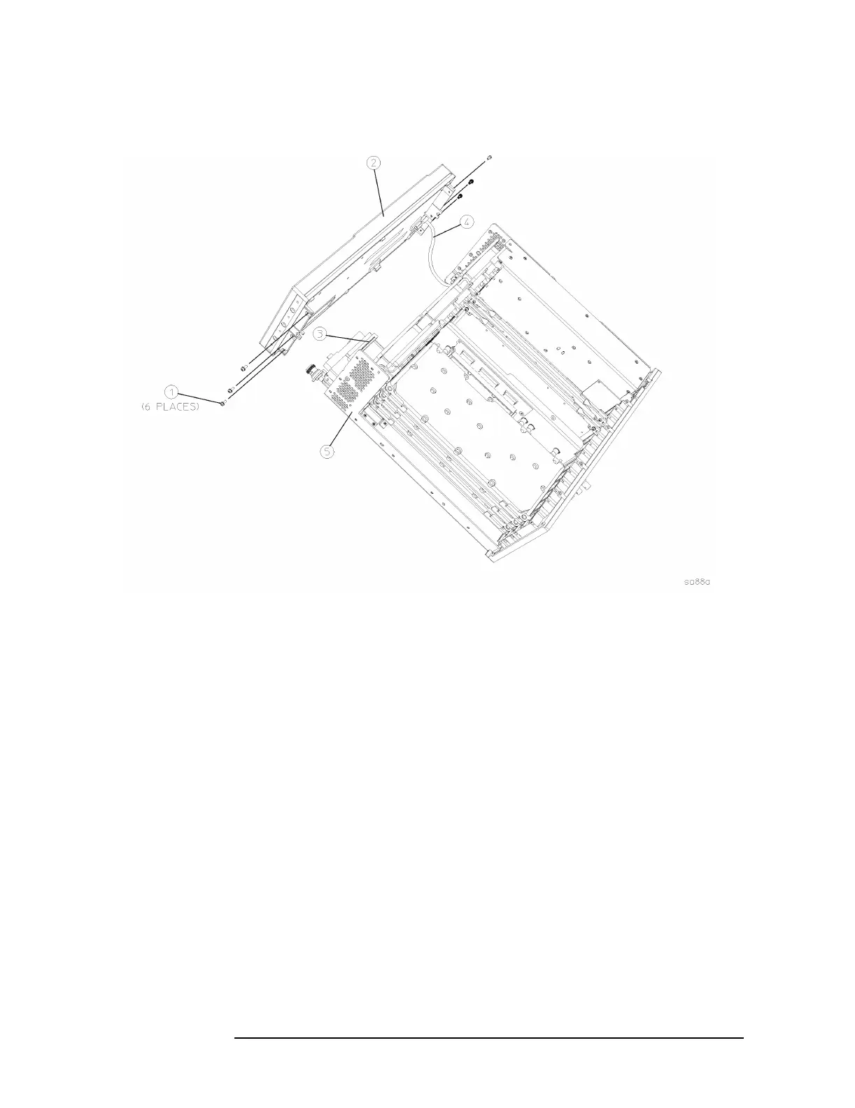
Figure 4-4 Front Frame Assembly Removal
Replacement
1. Place the front frame assembly in front of the deck.
2. Connect the ribbon cable (3) to the A3 front panel interface board.
3. Feed the coaxial cable BNC connector through the External Trigger
Input
hole in the front frame. Secure with the nut removed earlier,
using a 9/16’” socket. Torque to 21 inch pounds.
4. Clip the coaxial cable into the two cable clamps positioned on the
front frame shield.
5. Position the front frame on the deck using the alignment bosses on
the deck (5). Remember to tuck the ribbon cable under the fans
when pushing the frame onto the deck. This will insure proper
airflow to cool the instrument. Using the T-10 driver, replace the 6
screws (1) that secure the front frame to the deck. Torque to 9 inch
pounds.
6. Replace the instrument outer case. Refer to the “Instrument Outer
Case” replacement procedure.

 Loading...


