Chapter 4 179
Assembly Replacement
A4 Disk Drive and A5 Disk Drive Board
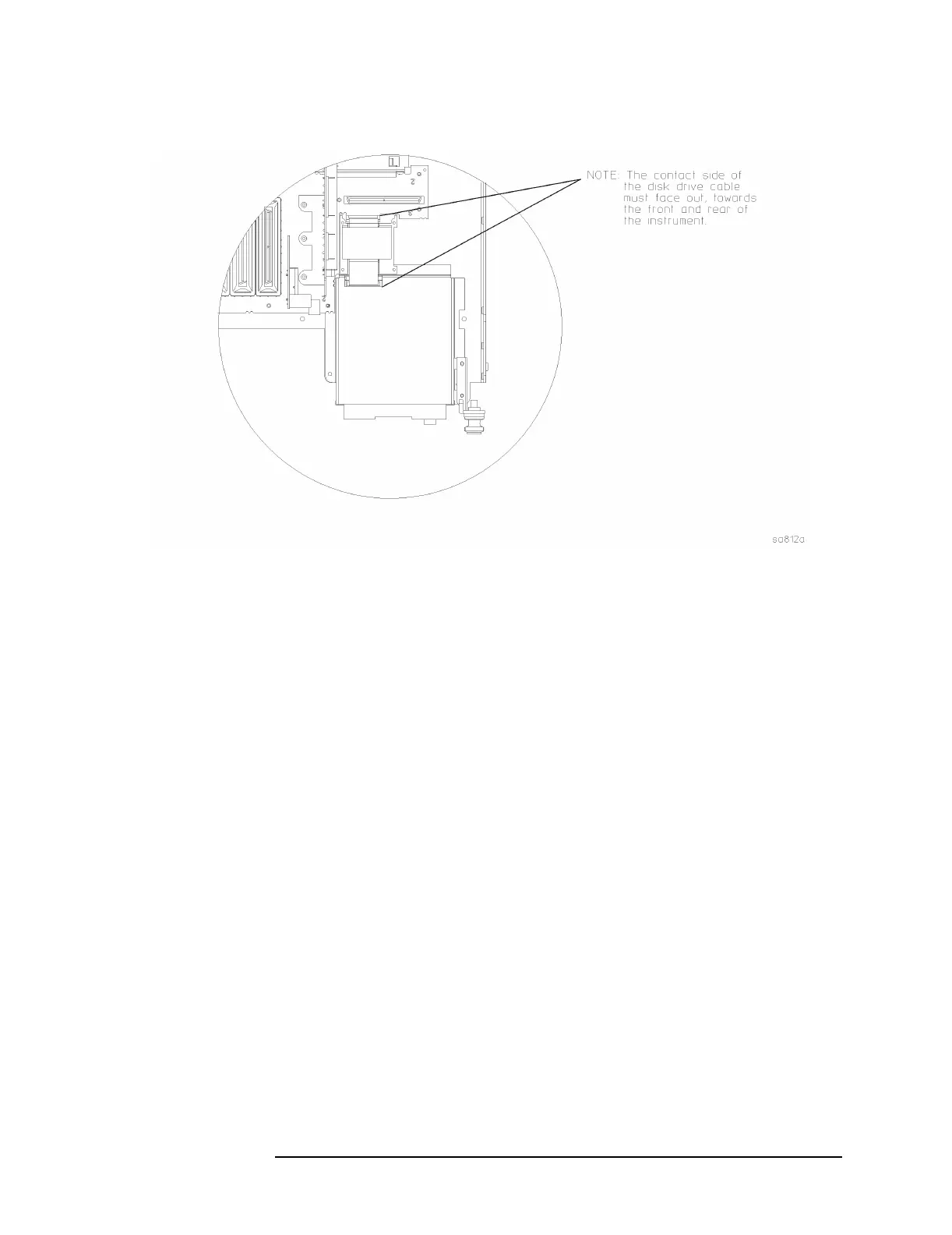
Figure 4-7 Disk Drive Flat Flex Cable
Replacement
1. To install the disk drive board (3) into the mount, align the pins on
the mount with the hole and the slot on the board. Refer to Figure
4-6.
2. Install the disk drive (2) into the mount over the pc board. Ensure
the drive is located over the pin at the rear of the mount. Place the
top cover of the disk mount over the 4 pins.
3. Refer to Figure 4-5. Slide the disk drive assembly into the disk
shield.
4. Plug in the flat flex cable to the disk drive and the motherboard.
Refer to Figure 4-7 for the proper orientation of the cable.
5. Refer to Figure 4-5. Place the disk cover over the ferrite shield.
Using the T-10 driver, replace the 4 screws. Torque to 9 inch pounds.
6. Plug the ribbon cable onto the motherboard.
7. Replace the front frame. Refer to the “Front Frame” replacement
procedure.
8. Replace the A17, A18, and A19 assemblies. Refer to “A17 RF, A18
Reference, and A19 Synthesizer Assemblies” replacement procedure.
9. Replace the instrument top brace. Refer to the “Top Brace”
replacement procedure.
 Loading...


