Chapter 1 39
Troubleshooting
Isolating an RF, Analog IF, Digital IF, Reference, Synthesizer, or CPU Problem
Isolating an RF, Analog IF, Digital IF,
Reference, Synthesizer, or CPU Problem
This section provides information and techniques for isolating
amplitude failures along the main signal path.
Verifying the A17 RF Assembly
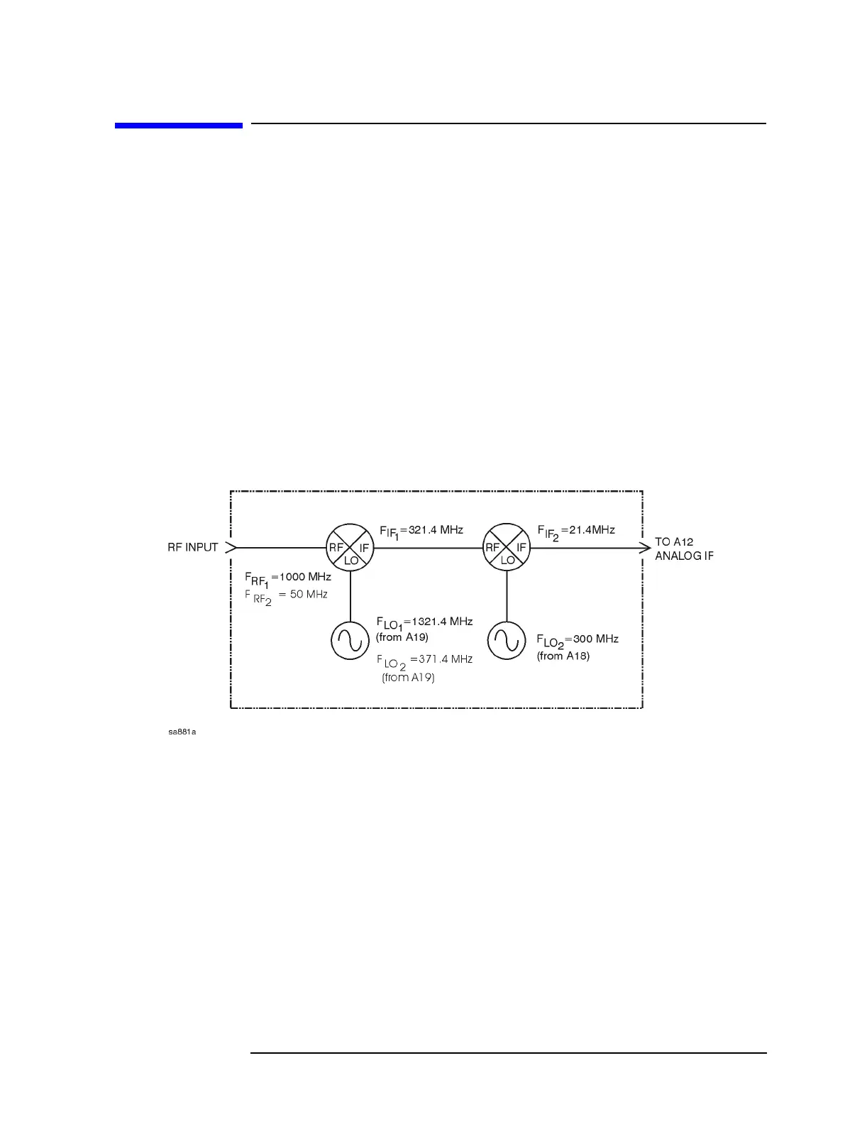
The A17 RF assembly uses two internal mixers to down-convert the
instrument’s input signal to the 2nd IF of 21.4 MHz. You can verify the
performance of the RF assembly by injecting a 50 MHz CW signal at the
front panel RF input connector, and measuring the 21.4 MHz output
signal level. The default attenuator setting is 0 dB. Refer to Figure 1-7
for two examples of the down conversion process; one with an input
frequency of 1000 MHz, and one with an input frequency of 50 MHz.
Figure 1-7 Example of Down Conversion

 Loading...


