Chapter 4 207
Assembly Replacement
A25 SCSI Board
A25 SCSI Board
CAUTION Use ESD precautions when performing this replacement procedure.
Removal
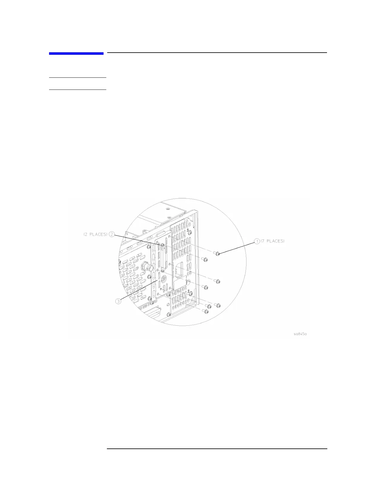
1. Refer to Figure 4-25. At the rear of the instrument, use a T-10 driver
to remove the 7 screws (1) securing the small panel to the frame.
2. The A25 board can be removed through the rear panel by pulling up
on the board to disengage it from the CPU board.
3. If the board hits the rear frame and will not come out, using the flat
blade screwdriver, remove the 2 screwlocks (2) that secure the dress
panel (3) to the A25 board.
Figure 4-25 SCSI Board Removal
Replacement
1. Replace the A25 board by inserting it into the opening on the rear
frame. Carefully position the board in the CPU board connector and
push down to mate.
2. Replace the panel onto the frame by replacing the 7 screws using a
T-10 driver. Torque to 9 inch pounds.
3. If the dress panel was removed in step 3 (above), replace the 2
screwlocks to secure the dress panel to the A25 board using the flat
blade screwdriver. Torque to 6 inch pounds.

 Loading...


