Chapter 4 205
Assembly Replacement
A22A1 DRAM, A22A2 Flash, and A22A3 GP-IB Capacitor Boards
A22A1 DRAM, A22A2 Flash, and A22A3 GP-IB
Capacitor Boards
CAUTION Use ESD precautions when performing this replacement procedure.
Removal
1. Remove the instrument top brace. Refer to the “Top Brace” removal
procedure.
2. Remove the A22 assembly. Refer to the “A22 Processor Assembly”
removal procedure.
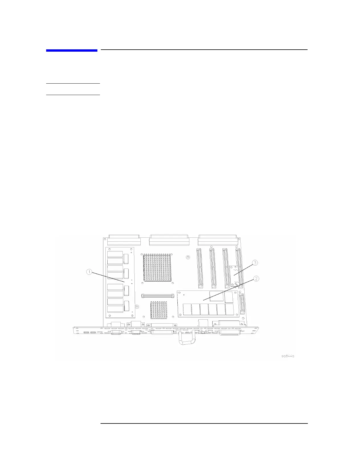
3. Refer to Figure 4-24. Pinch the standoffs and carefully pull up on
either the A22A1 DRAM board (1), or the A22A2 Flash board (2)to
disengage it from the processor assembly.
4. Instruments with serial prefix US3948 and below also have the
A22A3 GP-IB capacitor board. To remove the A22A3 GP-IB capacitor
board (3) carefully pull up on the board to disengage from the
processor board connector.
Figure 4-24 A22A1, A22A2, and A22A3 Board Removal

 Loading...


