34 Chapter 1
Troubleshooting
Power Supply Check
Power Supply Check
NOTE There are no fuses to replace within the power supply. If you determine
that the power supply is the failed assembly, replace the power supply.
Observing the LED on the front of the instrument, and measuring the
probe power connector, will determine if there is catastrophic failure in
the power supply assembly.
1. Ensure the instrument is plugged in with the power switch in the
Standby position (power not switched on). Verify that the yellow
LED next to the power switch is lit. A lit yellow LED indicates the
+15 VDC line (P15 STB) is providing enough voltage to light the
LED. (The actual voltage may not be +15 VDC.)
2. Power on the instrument and verify that the green LED on the front
panel is lit. A lit green LED indicates the power supply has received
an “ON” command and that the +5.2 VDC supply can at least light
the LED.
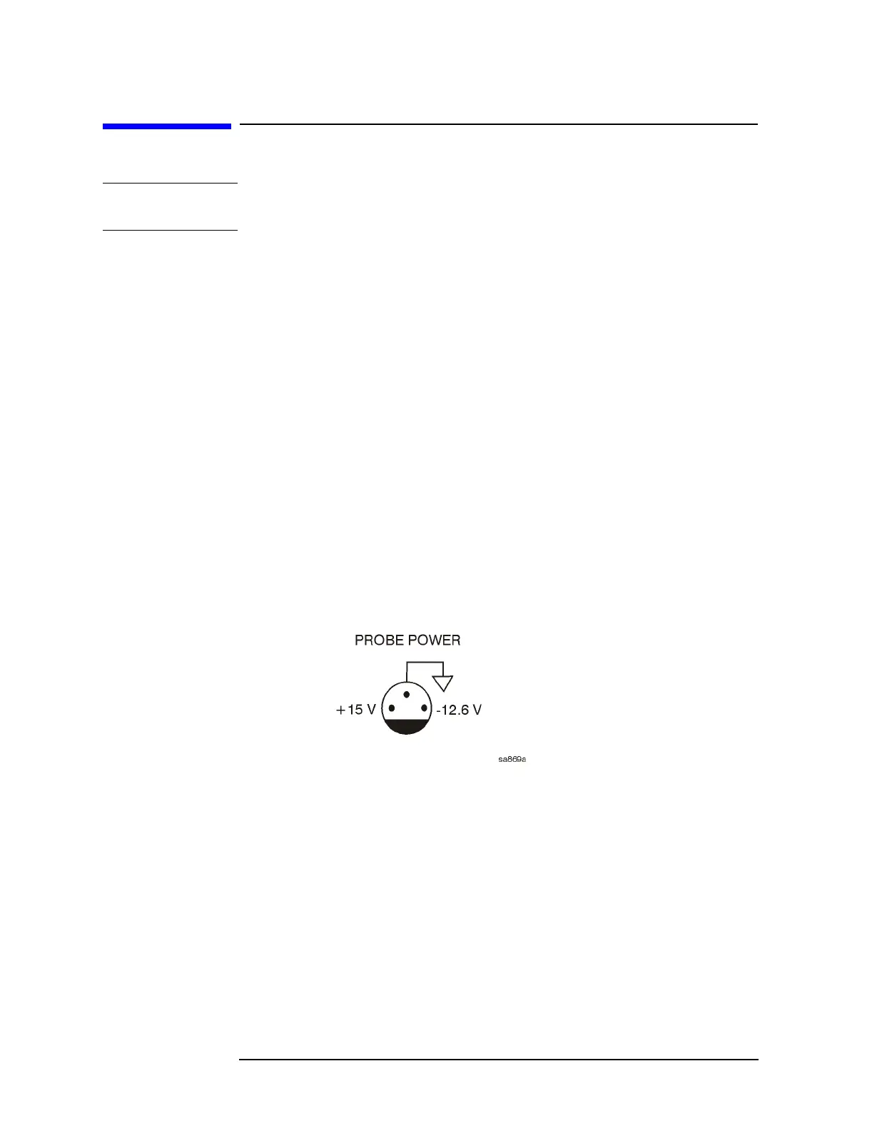
3. The front panel probe power connector can be used to check the
+15 VDC and −12.5 VDC (−15 VDC) supplies. The −12.5 VDC is
produced by post regulating the −15 VDC supply. Refer to Figure 1-5
for a diagram of the probe power connector.
Figure 1-5 Probe Power Connector
If all of these supplies seem dead, it is likely that the problem is a
defective A6 power supply assembly, or some other assembly is loading
down the A6 power supply. Continue with "If All Voltage Supplies Are
Dead" on page 37, to determine the cause of the problem.
If the correct LEDs are lit and the probe power voltages measure within
the specifications listed in the table below Figure 1-6 on page 36, the
power supply has not suffered a catastrophic failure; however, the
power supply could still be at fault. Continue with the next section to
measure the individual voltage supplies.

 Loading...


