192 Chapter 4
Assembly Replacement
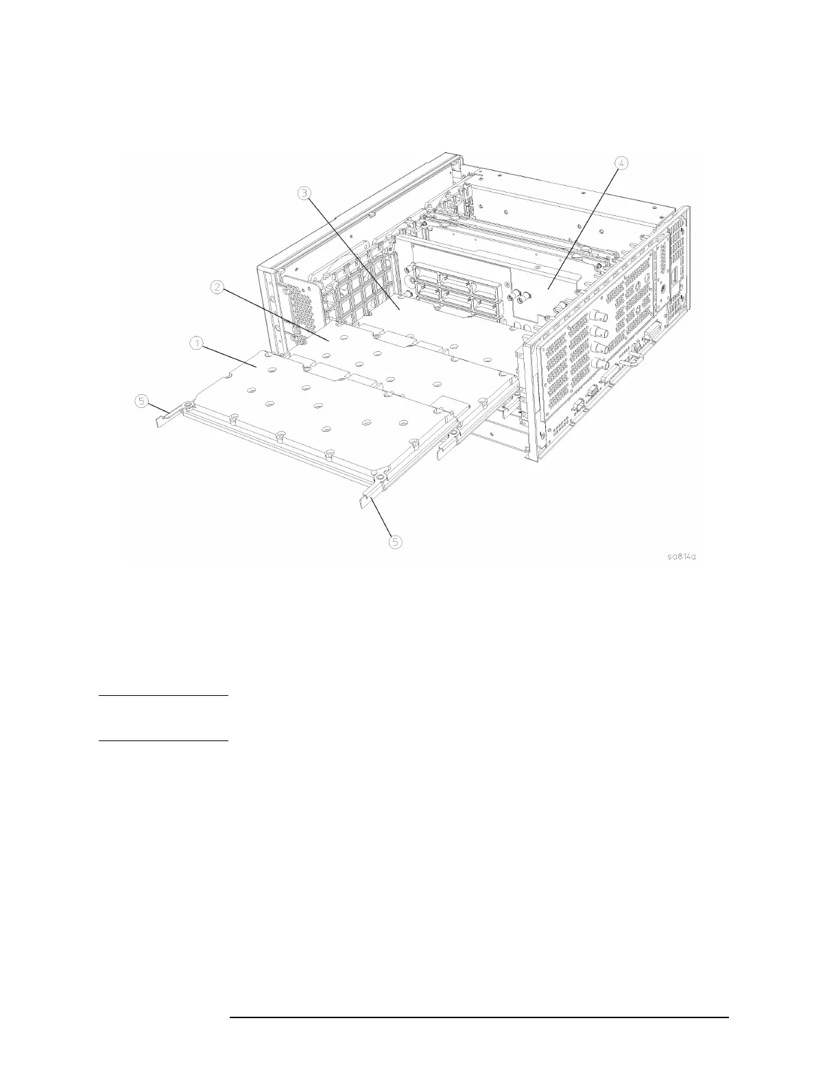
A17 RF, A18 Reference, and A19 Synthesizer Assemblies
Figure 4-16 A17, A18, A19 Removal
Replacement
1. Refer to Figure 4-16 or the diagram printed on the top brace for
correct placement of assemblies.
NOTE A rebuilt A19 synthesizer assembly may require the removal of a
“keying tab” before it can be inserted into the instrument.
2. Place the assembly into the slots on the mid-web and rear frame.
Hook the board ejectors over the vertical tabs.
3. Carefully slide the assembly into the daughter board and push on
the ejectors to engage the connectors. Make certain the rigid cables
attached to the center-web also engage the assemblies as they are
installed.
4. Replace the instrument top brace. Refer to the “Top Brace”
replacement procedure.
 Loading...


