230 Chapter 4
Assembly Replacement
Front Frame Subassemblies
Front Panel External Trigger Cable
Removal/Replacement
NOTE The front panel External Trigger connector/cable must be replaced as
an assembly.
CAUTION Be careful to not scratch the dress panel when removing or replacing
this part.
1. Remove the front frame assembly. Refer to the “Front Frame”
removal procedure on page 175.
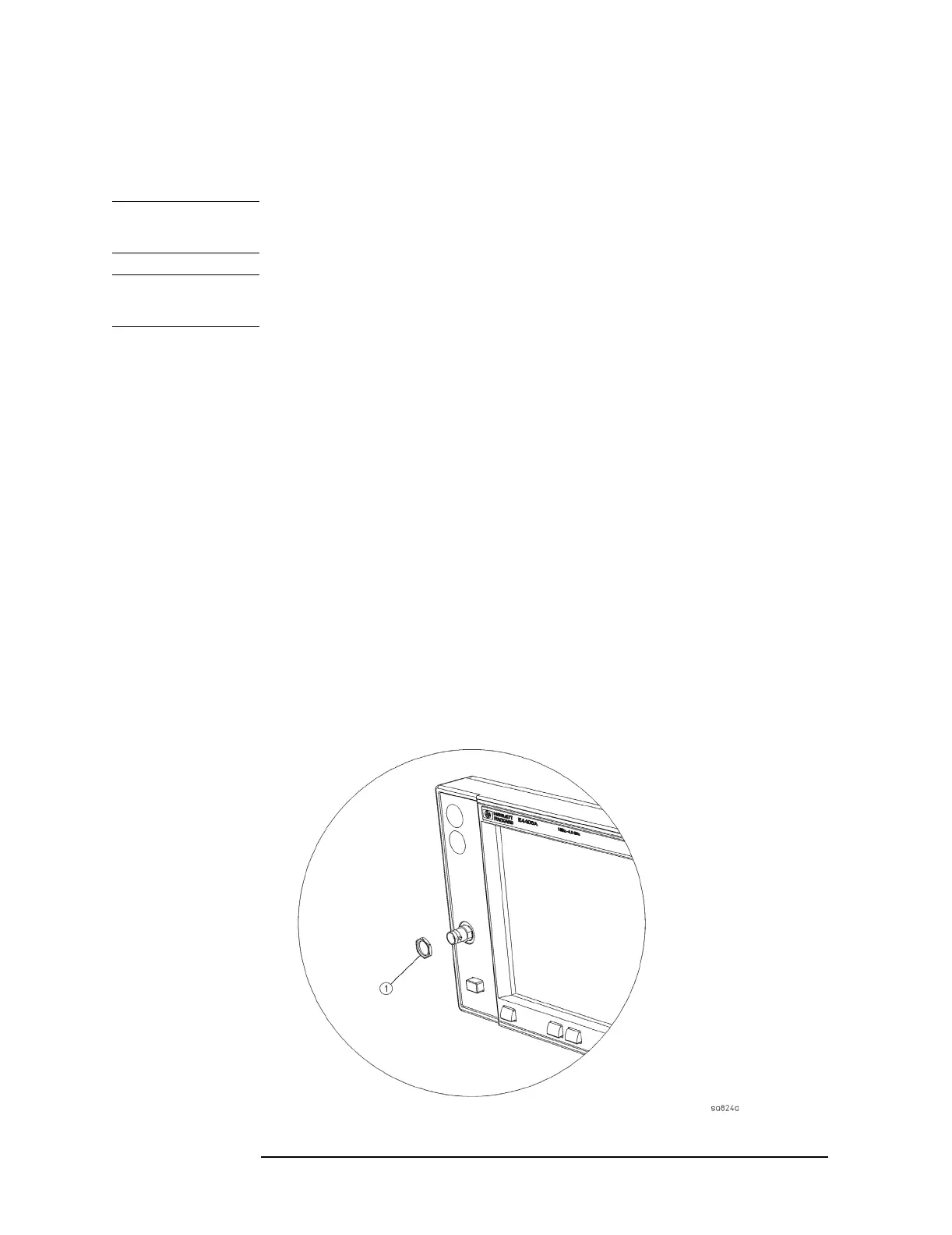
2. Refer to Figure 4-40. Using the 9/16 socket, remove the nut (1) that
secures the connector to the front frame.
3. Disconnect the cable from the A12 analog IF assembly.
4. For replacement, position the connector/cable through the front
frame.
5. Using the 9/16 socket, replace the nut to secure the connector to the
front frame. Torque to 21 inch pounds.
6. Clip the cable into the cable clamps on the shield.
7. Re-route the cable to avoid interference with the fans or the airflow,
and reconnect to the A12 analog IF assembly.
8. Replace the front frame. Refer to the “Front Frame” replacement
procedure.
Figure 4-40 Front Panel External Trigger Input Connector Removal

 Loading...


