Chapter 4 211
Assembly Replacement
Rear Frame
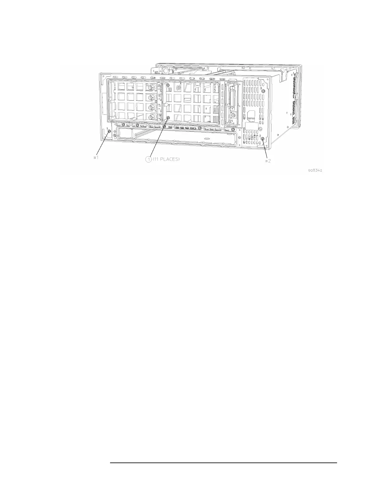
Figure 4-27 Rear Frame Removal
Replacement
1. Place the rear frame in position on the deck.
2. Using the T-10 driver, replace the 11 screws to secure the rear frame
to the deck. For alignment purposes, tighten the screws marked with
a #1 and a #2 in Figure 4-27. Torque to 9 inch pounds.
3. Replace the rear dress panel and reroute the External Trigger Input
cable. Using the T-10 driver, replace the 13 screws that secure the
dress panel to the rear frame. For alignment purposes, tighten the
screws marked with a #1 and a #2 (silkscreened on the dress panel)
first. Torque to 9 inch pounds.
4. Re-attach the flat flex cable from the daughter board to the rear
panel connector board.
5. Replace the A22 processor assembly. Refer to the “A22 Processor
Assembly” replacement procedure.
6. Replace the A25 SCSI board. Refer to the “A25 SCSI Board”
replacement procedure.
7. Replace the A10 and the A12 assemblies. Refer to the “A10 Digital
IF and A12 Analog IF Assemblies” replacement procedure.
8. Replace the A7 assembly (if installed). Refer to the “A7 Baseband I/Q
Assembly (Option B7C)” replacement procedure.
9. Replace the A17, A18, and A19 assemblies. Refer to the “A17 RF,
A18 Reference, and A19 Synthesizer Assemblies” replacement
procedure.
10.Replace the instrument top brace. Refer to the “Top Brace”
replacement procedure.

 Loading...


