226 Chapter 4
Assembly Replacement
Front Frame Subassemblies
Bezel and Keypad
Removal
1. Remove the display/rubber mount assembly. Refer to the first section
of the “Display Removal” procedure.
2. Remove the front panel interface board. Refer to the “A3 Front Panel
Interface Board” removal procedure.
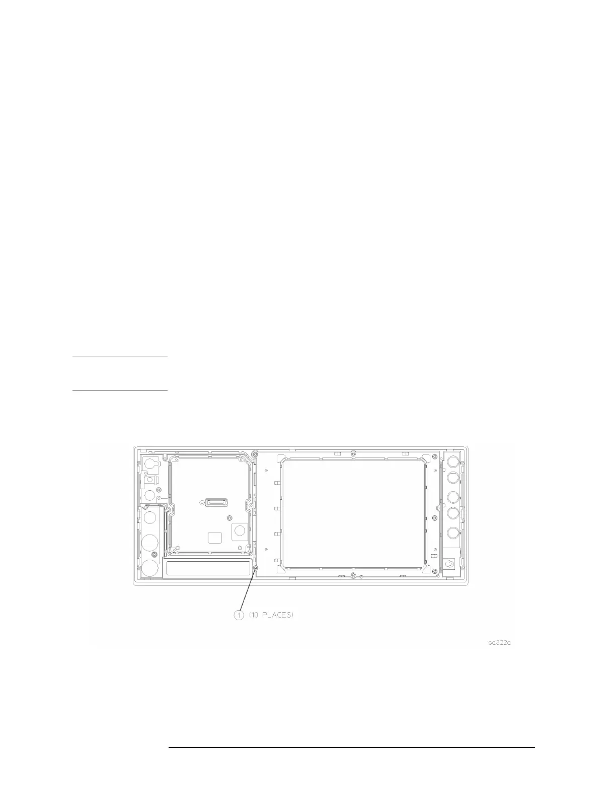
3. Refer to Figure 4-38. Using the T-10 driver, remove the 10 screws
(1) that secure the bezel and keyboard assembly to the front frame.
4. Refer to Figure 4-39. The 10 screws also attach the dress panel,
bezel, subpanel, keypad, and keyboard to the front frame. Take care
to keep these parts in the correct order and aligned properly.
5. Lift the front frame off of the keypad/keyboard assembly.
6. The bezel and keyboard can now be separated by pressing on the pin
just above the
On/Standby LEDs on the bezel and sliding apart to
unlock the tabs. The flexible keypads can be separated from the
keyboard and the bezel by pulling them apart.
NOTE Take care to not touch the contacts on the keypads. Contaminants on
the contacts might interfere with the performance of the key.
Figure 4-38 Keypad Removal

 Loading...


