208 Chapter 4
Assembly Replacement
A27 Rear Panel Connector Board
A27 Rear Panel Connector Board
CAUTION Be careful to not scratch the dress panel when removing or replacing
this part.
Removal
1. Remove the instrument outer case. Refer to the “Instrument Outer
Case” removal procedure.
2. Remove the top brace. Refer to the “Top Brace” removal procedure.
3. Remove the A17, A18, and A19 assemblies. Refer to “A17 RF, A18
Reference, and A19 Synthesizer Assemblies” removal procedure.
4. Disconnect the ribbon cable from the daughterboard.
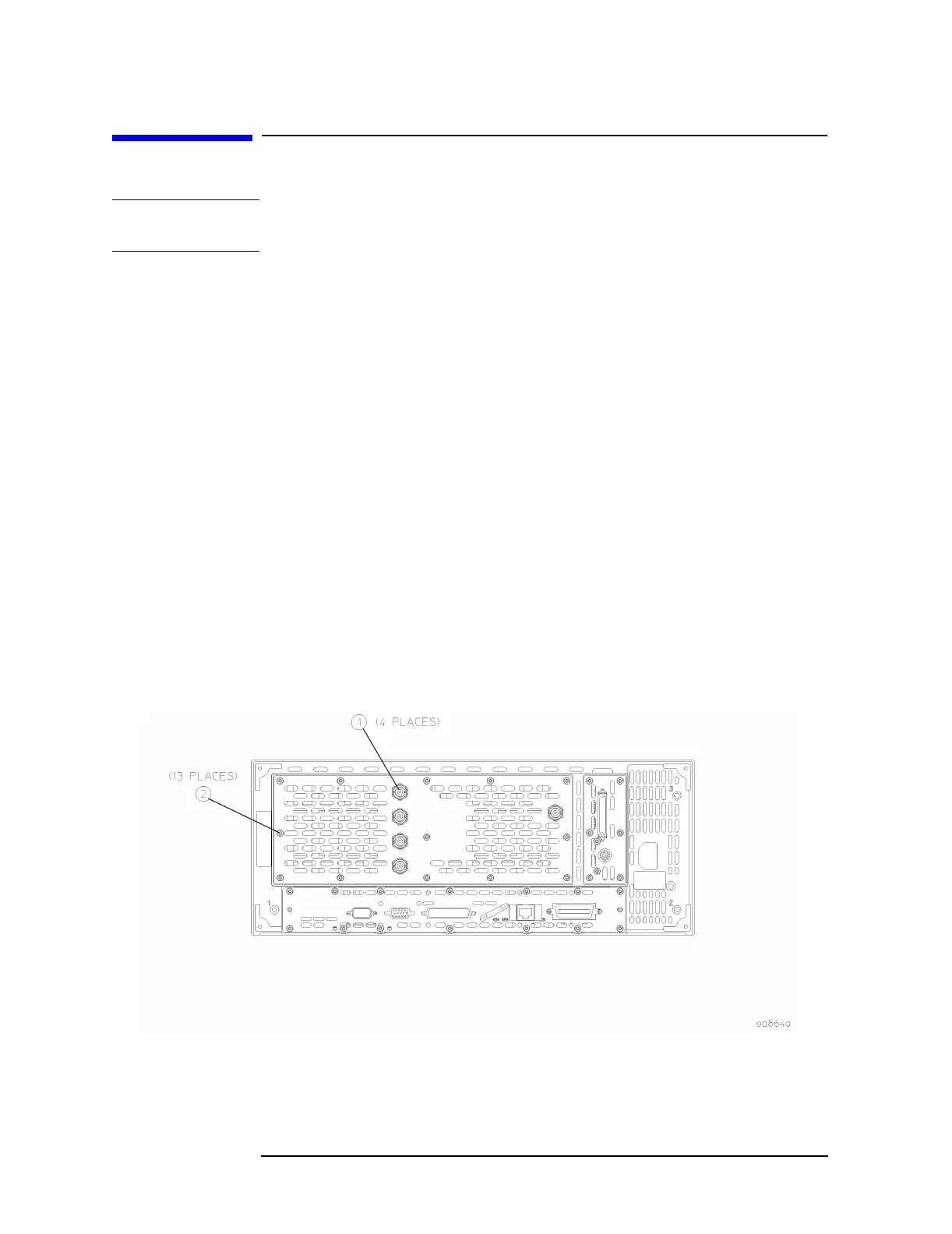
5. Refer to Figure 4-26. Using the 9/16 open-end wrench, remove the
four nuts (1) that secure the rear panel connectors to the rear
frame.
6. Using the T-10 driver, remove the 13 screws (2) to remove the rear
dress panel.
Figure 4-26 Rear Panel Connector Board Removal

 Loading...


