184 Chapter 4
Assembly Replacement
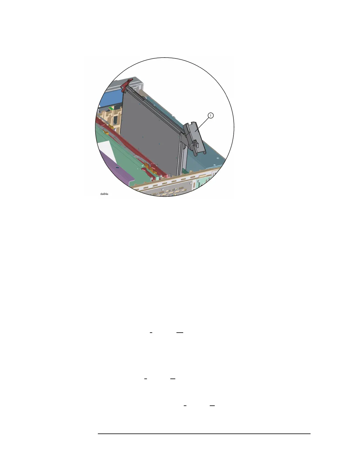
A7 Baseband I/Q Assembly (Option B7C)
Figure 4-11 A7 Assembly with Baseband I/Q Rear Ejector
Replacement
Step 1. Insert the A7 assembly into the instrument
1. Slide the A7 assembly into the front and rear guides of slot 0 ( Note:
if the A7 assembly was retrofitted into the instrument, the A7
assembly may be located in slot 1; in this case the A7 assembly will
have a standard rear ejector, not the large rear ejector shown as item
1 in Figure 4-11).
2. Carefully insert the baseband I/Q assembly ejectors into from the
motherboard.
3. Hook the front and rear ejectors under the tabs that are located on
the rear frame and mid web of the instrument.
Step 2 Attach the Baseband I/Q Cable Assembly
1. Connect the I, I
, Q, and Q cables to their respective connectors on the
top-front of the A7 assembly, if they are not already connected.
2. Attach the four, bundled I/Q wires to the cable clip (1400-3014) that
is located on the rear of the front panel assembly, as shown in item 5
of Figure 4-9.
3. Insert the I, I
, Q and Q cables into their respective openings in the
rear of the front panel assembly. These openings are labelled.
4. Use the 9/16 deep socket nut driver to secure the four 15/32-32 hex
nuts (2950-0035) to the I, I
, Q and Q connectors on the front panel.
See item 1 in Figure 4-10.

 Loading...


