180 Chapter 4
Assembly Replacement
A6 Power Supply
A6 Power Supply
CAUTION Use ESD precautions when performing this replacement procedure.
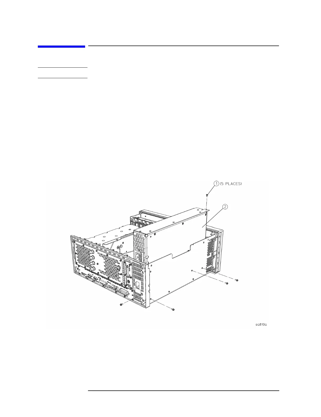
Removal
1. Remove the instrument top brace. Refer to the “Top Brace” removal
procedure.
2. Refer to Figure 4-8. Using the T-10 driver, remove the 5 screws (1)
securing the A6 power supply assembly (2)to the deck and the rear
frame.
3. Carefully pull up on the power supply assembly to disengage from
the motherboard connector.
Figure 4-8 Power Supply Removal

 Loading...


