186 Chapter 4
Assembly Replacement
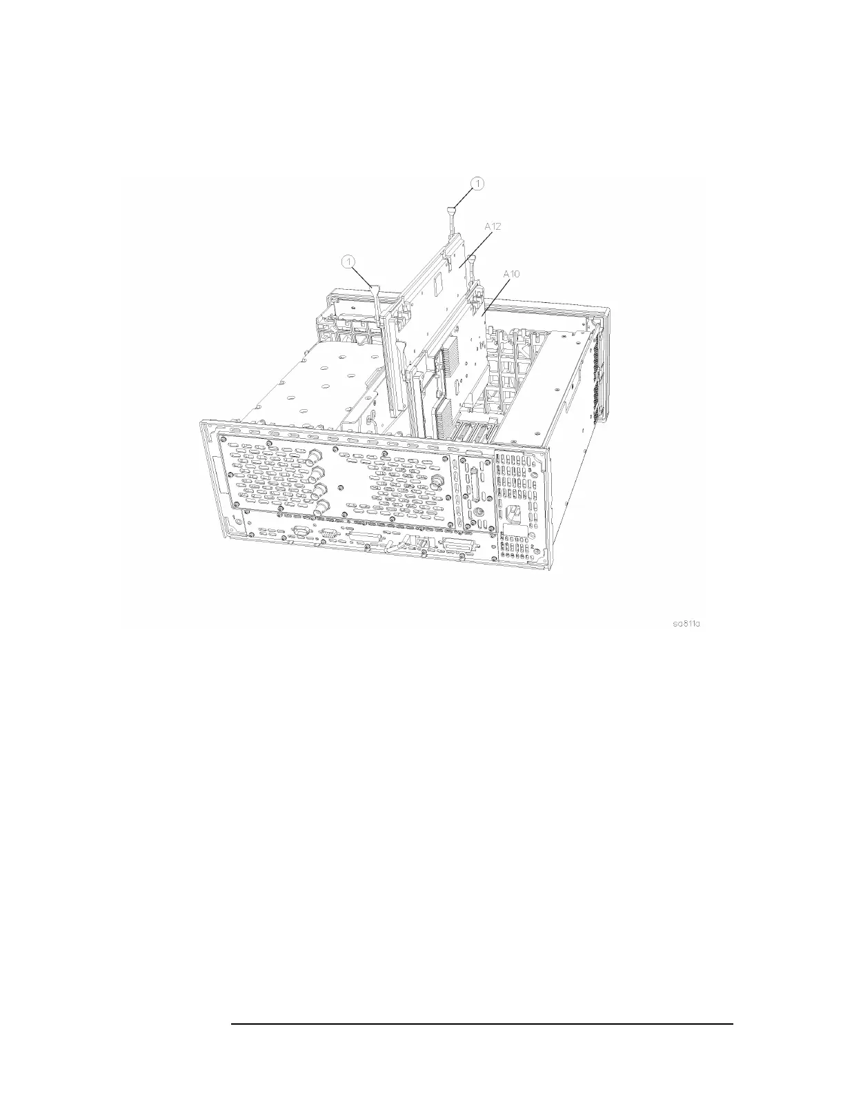
A10 Digital IF and A12 Analog IF Assemblies
Figure 4-13 Digital IF and Analog IF Assembly Removal
Replacement
1. Slide the assembly down in the correct front and rear guide slots.
Refer to the silkscreened locations on the motherboard or the top
brace to ensure correct placement of the assemblies. Hook the
ejectors under the tabs on the rear frame and mid web. Carefully
push down on the ejectors to mate the assembly with the
motherboard connectors.
2. Reconnect the coaxial cables that were removed. Replace the cables
to the correct connectors. Refer to the silkscreen on the instrument
top brace for correct placement of cables. Take care to dress the
cables correctly so they aren’t pinched when the top brace is
replaced.
3. Replace the instrument top brace. Refer to the “Top Brace”
replacement procedure.
 Loading...


