190 Chapter 4
Assembly Replacement
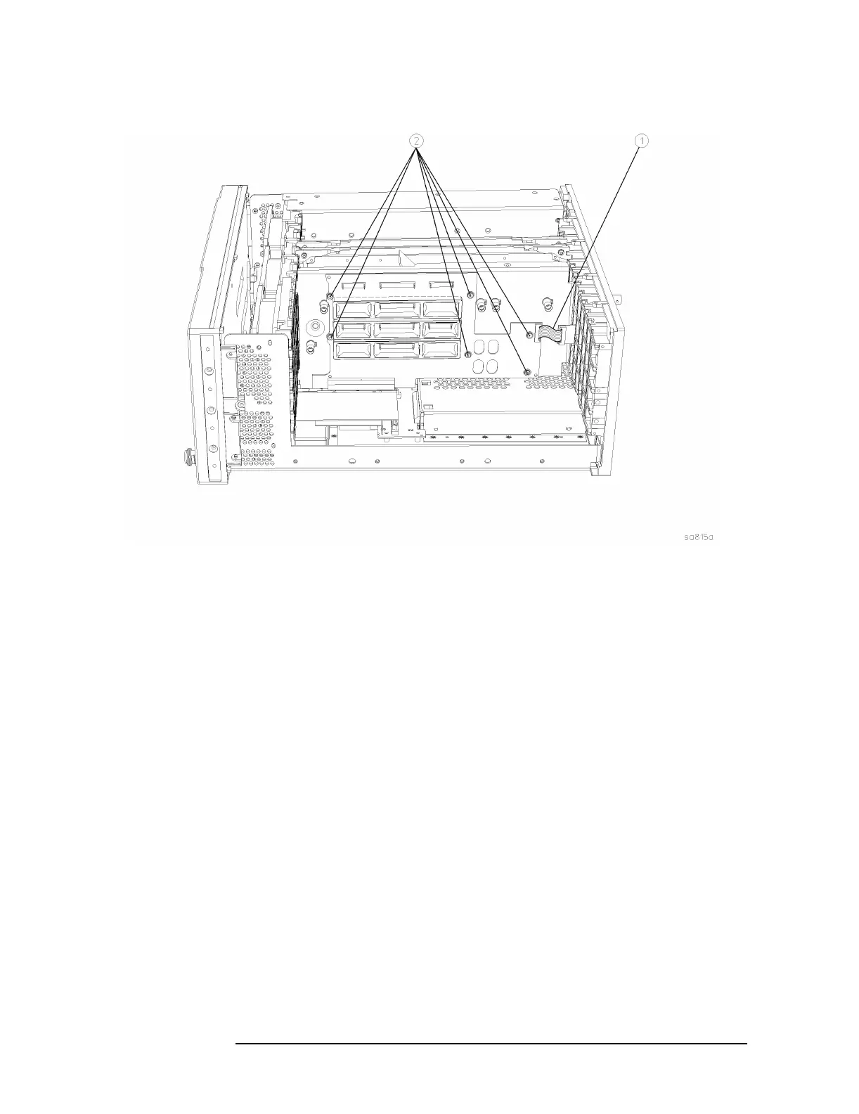
A15 Daughter Board
Figure 4-15 Daughter Board Removal
Replacement
1. Position the daughter board connector over the motherboard
connector and carefully press down to mate the connectors.
2. Refer to Figure 4-15. Using the T-10 driver, replace the 6 screws that
secure the daughter board to the center web. For alignment
purposes, tighten the screws marked with a #1 and a #2 (marked on
the daughter board) first, then tighten the remaining screws. Torque
to 9 inch pounds.
3. Reconnect the flat flex cable to the daughter board. Lock the
connector.
4. Replace the A17, A18, and A19 assemblies. Refer to the “A17 RF,
A18 Reference, and A19 Synthesizer Assemblies” replacement
procedure.
5. Replace the instrument top brace. Refer to the “Top Brace”
replacement procedure.
 Loading...


