224 Chapter 4
Assembly Replacement
Front Frame Subassemblies
A3 Front Panel Interface Board
Removal
1. Remove the RPG knob by pulling straight off of the control shaft.
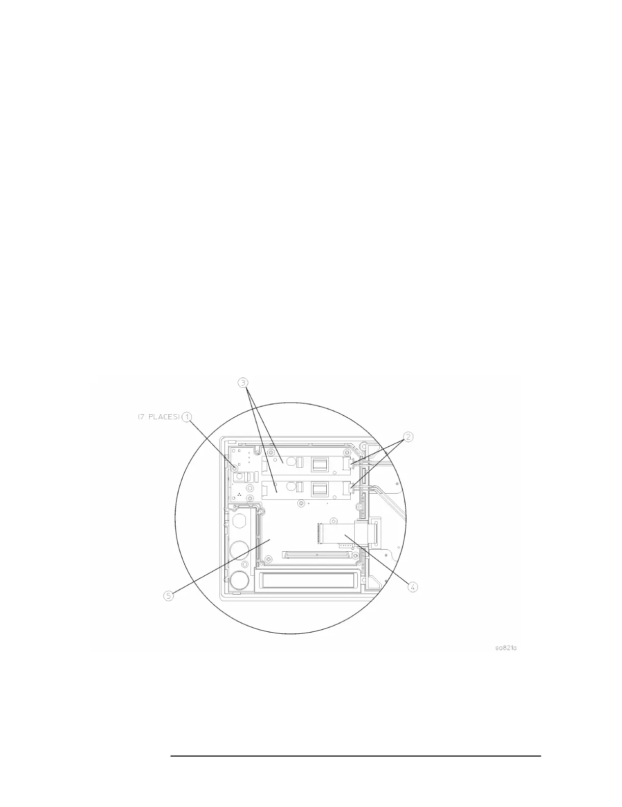
2. Refer to Figure 4-37. Disconnect both of the 2-wire backlight cables
(2) from the inverter boards (3).
3. Unplug the display flat flex cable (4) from the front panel interface
board. To do this, you must first pull up on both sides of the locking
mechanism of the ribbon cable connector. If not carefully inserted,
display problems may result.
4. Using the T-10 driver, remove the 7 screws (1) that secure the front
panel interface board (5) to the front frame assembly.
5. Lift the front panel interface board from the front frame assembly.
Figure 4-37 A3 Front Panel Interface Board Removal
 Loading...


