Chapter 4 185
Assembly Replacement
A10 Digital IF and A12 Analog IF Assemblies
A10 Digital IF and
A12 Analog IF Assemblies
CAUTION Use ESD precautions when performing this replacement procedure.
Removal
1. Remove the instrument top brace. Refer to the “Top Brace” removal
procedure.
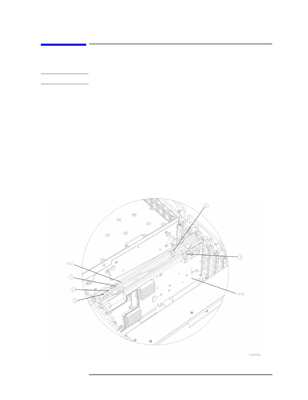
2. Refer to Figure 4-12. Remove the coaxial cables at the locations
indicated. To remove the A10 digital IF assembly, disconnect the
cable (1) from the A10 board. To remove the A12 analog IF
assembly, disconnect the cables (1), (2), (3), and (4) from the A12
board.
3. Refer to Figure 4-13. Carefully pull up on the ejectors (1) to
disengage the assembly from the connectors and remove from the
deck.
Figure 4-12 Cable Locations

 Loading...


