Chapter 4 183
Assembly Replacement
A7 Baseband I/Q Assembly (Option B7C)
item 5 of Figure 4-9.
3. Use the 9/16 deep socket nut driver to remove the four 15/32-32 hex
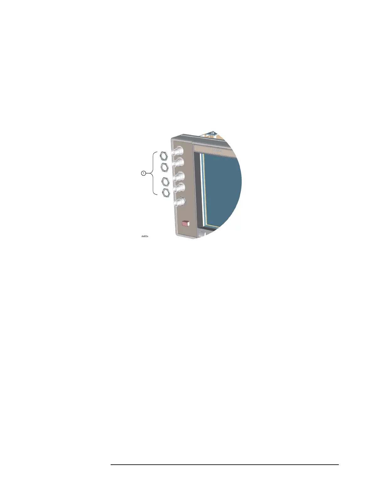
nuts (2950-0035) that secure the I/Q baseband connectors to the
front panel. See item 1 in Figure 4-10.
Figure 4-10 Front Panel Baseband I/Q Connectors
4. Remove the baseband I/Q cable connectors through the rear of the
front panel assembly.
Step 5. Remove the A7 assembly from the instrument
1. Carefully pull up on the baseband I/Q assembly ejectors to detach
the A7 assembly from the motherboard.
2. Unhook the front and rear ejectors under the tabs that are located on
the rear frame and mid web of the instrument.
3. Slide the A7 assembly out of the front and rear guides of slot 0.
(Note: if the A7 assembly was retrofitted into the instrument, the A7
assembly may be located in slot 1; in this case the A7 assembly will
have a standard rear ejector, not the large rear ejector shown as item
1 in Figure 4-11).

 Loading...


