38 Chapter 1
Troubleshooting
Power Supply Check
NOTE To further isolate the failure in the four remaining “minimum
assemblies”, measure the resistance (with the power turned off) from
the power supply test points on the digital IF extender board to ACOM
on the extender board. Make the measurements with the digital IF
board removed from the extender board.
Refer to Figure 1-6.
Check for shorts (zero Ω) or very low resistance (approx. 1 Ω). If a short
or low resistance is measured, pull the remaining boards from the
instrument in the following order, and recheck the shorted test point
after each board is pulled. Note that the resistance will be different
from the table, but you should be able to tell if the shorted condition has
changed. First pull the A14 fan control board, followed by the A22 CPU
assembly, and finally the A6 power supply.
If All Voltage Supplies Are Good
If all of the supplies have measured within tolerances, and the
instrument still appears dead, refer to "Verifying the A22 CPU
Assembly" on page 54 and troubleshoot the A22 CPU assembly.
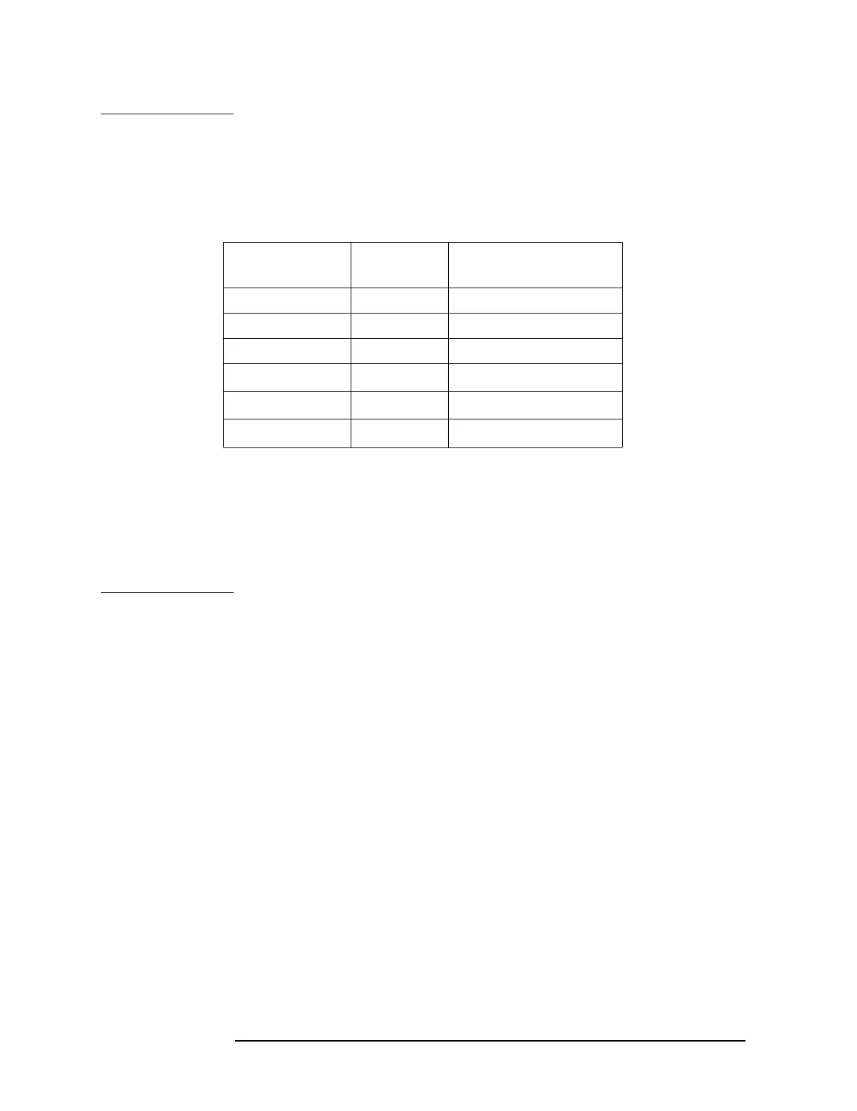
Measurement
Location
Supply Approximate Resistance
(Ω)
A+5.2 VDC 41
B −5.2 VDC 47
C +15 VDC 366
D −15 VDC
141
E+9 VDC
78
F +32 VDC
939
 Loading...


