196 Chapter 4
Assembly Replacement
Mid Web/Fans
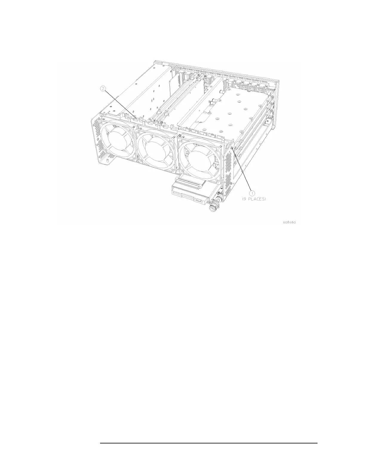
Figure 4-18 Mid-Web/Fan Assembly Removal
Replacement
1. Using the T-10 driver, replace the 9 screws that secure the
mid-web/fan assembly to the deck. Torque to 9 inch pounds. Be
careful to avoid pinching the fan cables.
2. Plug the 3 fan connectors into the motherboard.
3. Carefully rotate the semi-rigid cable down and place the cable under
the 2 hooks on the mid web. Using the T-10 driver, secure the RF
input bracket to the deck with the 2 screws. Torque to 9 inch pounds.
4. Replace the power supply. Refer to the “A6 Power Supply”
replacement procedure.
5. Replace the A10 and the A12 assemblies. Refer to the “A10 Digital
IF and A12 Analog IF Assemblies” replacement procedure.
6. Replace the A7 assembly (if installed). Refer to the “A7 Baseband I/Q
Assembly (Option B7C)” replacement procedure.
7. Replace the A17, A18, and A19 assemblies. Refer to the “A17 RF,
A18 Reference, and A19 Synthesizer Assemblies” replacement
procedure.
8. Redress the coaxial cables in the mid-web.
9. Replace the front frame assembly. Refer to the “Front Frame”
replacement procedure.

 Loading...


