42 Chapter 1
Troubleshooting
Isolating an RF, Analog IF, Digital IF, Reference, Synthesizer, or CPU Problem
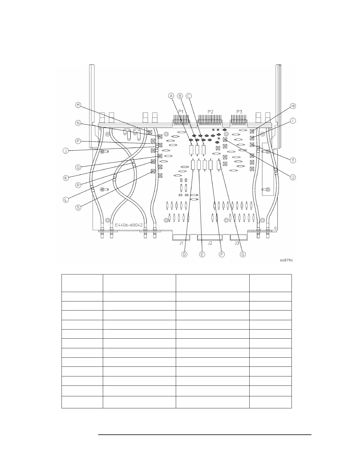
Figure 1-8 E4406-60042 Extender Board Measurement Locations
Measurement
Location
Signal Description Test Equipment Used Expected
Level
Apower supply DVM −15 VDC
Bpower supply DVM −5.2 VDC
Cpower supply DVM +15 VDC
Dpower supply DVM −6 VDC
Epower supply DVM +9 VDC
Fpower supply DVM +32 VDC
G power supply DVM +5.2 VDC
H 300 MHz 2nd L.O. In calibrated spectrum analyzer −8.75 dBm
I 50 MHz Internal Calibrator calibrated spectrum analyzer −18.4 dBm
J 321.4 MHz 1st IF Out calibrated spectrum analyzer −29 dBm
K RF Input calibrated spectrum analyzer −32 dBm
L
a
a. Remember to measure on the LO board side of the cable and not the RF board side.
371.4 MHz 1st LO Input calibrated spectrum analyzer +11.4 dBm

 Loading...


