Chapter 1 57
Troubleshooting
Isolating an RF, Analog IF, Digital IF, Reference, Synthesizer, or CPU Problem
CPU Assembly Detailed Troubleshooting
There are a few items that should be checked before suspecting a
defective A22 CPU assembly. The CPU must have all the DC power
supplies coming from the A6 power supply assembly through the A21
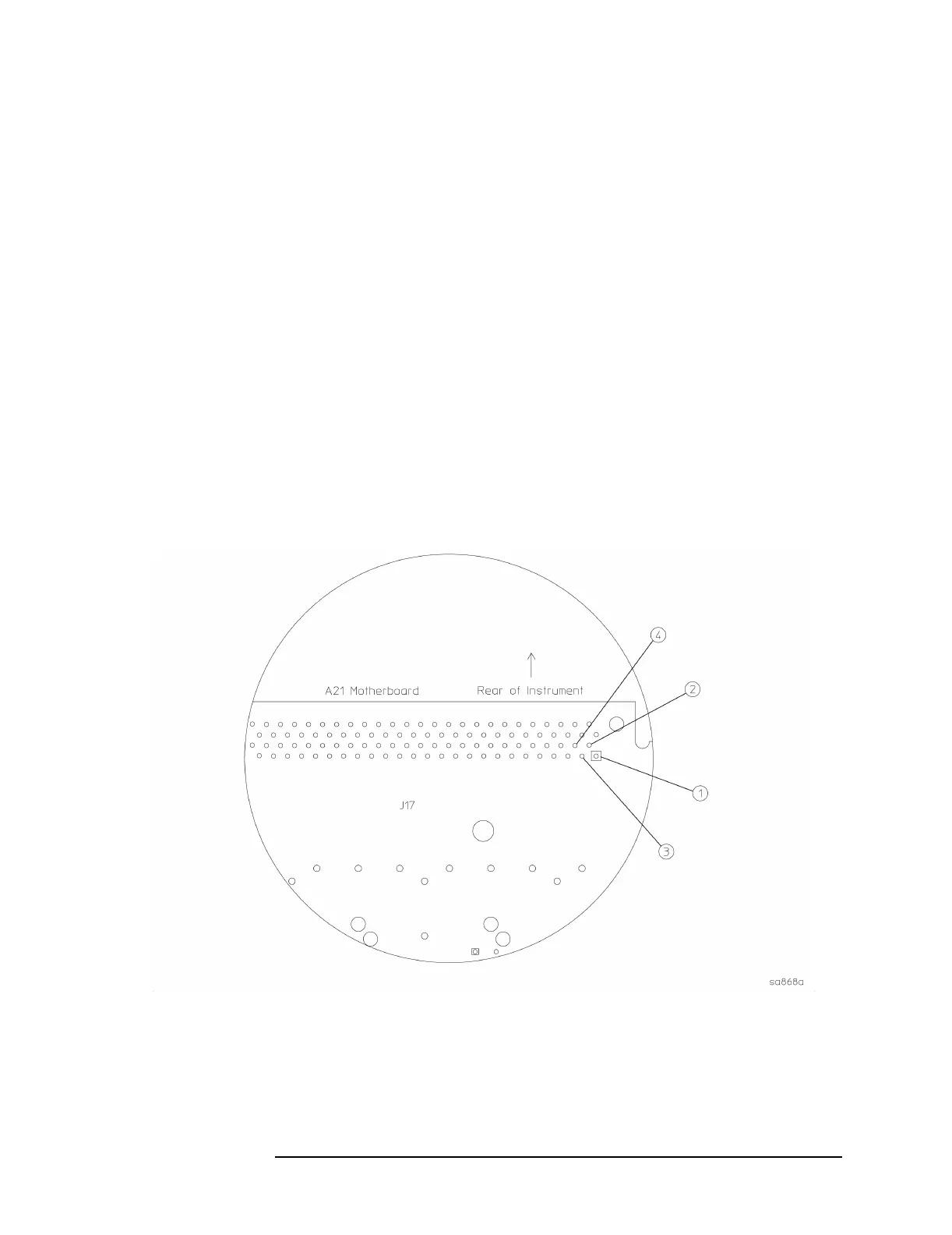
motherboard. Carefully measure the DC supplies on A21J17. Pins 1
and 2 should measure −12 VDC. Pins 3 and 4 should measure +12 VDC.
If the power supplies measure correctly, and the CPU does not boot
properly, the I/O lines could be loaded down by another assembly, or a
clock signal could be missing. Remove the A10 digital IF assembly and
try rebooting. The A12 analog IF assembly must be installed and
providing the 30 MHz sample clock before the CPU will boot. See the
previous page for troubleshooting hints.
If the instrument will still not boot, suspect the A22 processor assembly
is faulty.
Figure 1-16 Motherboard Test Points

 Loading...


