146 FieldFox User’s Guide
10. Connect an unterminated, longer cable to the FieldFox PORT 1 connector.
11. Observe the displayed phase difference between the reference cable and the
untrimmed cable.
NOTE The VVM phase reading shows a maximum of ±180°. Therefore, the electrical
length of the untrimmed cable MUST be within 180° of the reference cable.
12. Carefully trim the cable until the phase shift reads zero. The attached cable’s
electrical length is now matched to the reference cable.
13. Repeat steps 10 through 12 for the remaining cables to be trimmed.
2-Port Transmission Measurements
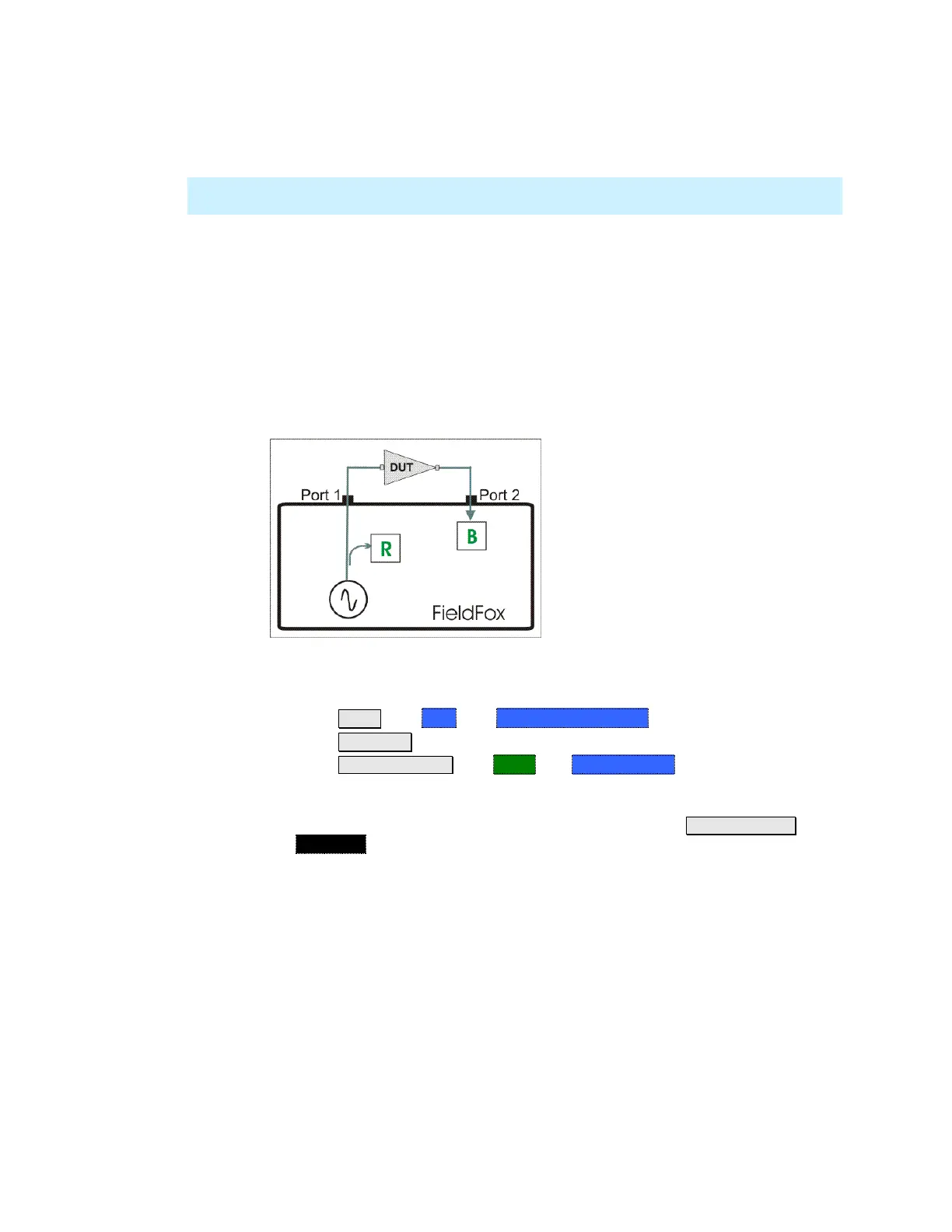
A 2-Port Transmission measurement is used for measuring electrical length,
insertion loss, gain, or isolation of a DUT at a single CW frequency. The FieldFox
signal source is transmitted out the port 1 connector, through the DUT, and into
the port 2 connector. In the following image, the gain of an amplifier is being
measured.
2-Port Transmission measurement of an amplifier
How to make a 2-Port Transmission Measurement
1. Press Mode then VVM then 2-Port Transmission.
2. Press Freq/Dist and enter the measurement frequency.
3. Press Meas Setup 4 then More then Output Power. Select High for
passive devices. Select Low for amplifiers.
4. Calibrate the FieldFox using one of the methods described on page 144.
Before performing a QuickCal or Mechanical Cal, press Meas Setup 4 then
Zero OFF.
5. Connect the DUT.
Notes:
The magnitude value is the gain (positive value) or the loss (negative value) of
the DUT.
The phase value is the difference in phase (in degrees) between the DUT input
and output.
To measure isolation of the amplifier, reverse the connection to the amplifier
(PORT 1 to the amplifier output).
 Loading...


