EasyManuals Logo
Home>Agilent Technologies>Measuring Instruments>FieldFox N9913A

Agilent Technologies FieldFox N9913A User Manual

Agilent Technologies FieldFox N9913A
219 pages
To Next Page IconTo Next Page
To Previous Page IconTo Previous Page
Page #16 background imageLoading...
Page #16 background image
16 FieldFox User’s Guide
Top Panel
Caption
Description
Learn More
Port 1
RF Output
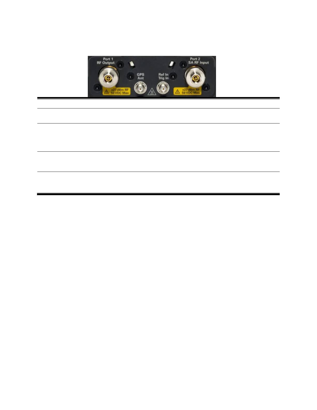
For CAT and NA measurements, use to make reflection measurements.
Maximum: ±50 VDC, +27 dBm RF
CAT Mode on page 20
NA Mode on page 38
Port 2
SA RF Input
For SA, use to make all measurements.
For CAT, NA, and VVM mode, use to make Port 2 transmission
measurements.
Maximum: ±50 VDC, +27 dBm RF.
SA Mode on page 75
GPS Ant
For use with built-in GPS. Produces a 3.3 VDC bias voltage for the antenna
pre-amplifier. Use with a GPS antenna such as N9910X-825. Other GPS
antennas can also be used.
GPS on page 179.
Ref In
Trig In
Frequency Reference Source and External Trigger Input signal.
Maximum: 5.5 VDC.
Freq. Ref on page 181.
Ext Trig (SA Mode) on
page 94

Table of Contents

Questions and Answers:

Question and Answer IconNeed help?

Do you have a question about the Agilent Technologies FieldFox N9913A and is the answer not in the manual?

Agilent Technologies FieldFox N9913A Specifications

General IconGeneral
BrandAgilent Technologies
ModelFieldFox N9913A
CategoryMeasuring Instruments
LanguageEnglish

Related product manuals