80 FieldFox User’s Guide
o Use the ▲|▼ arrows to increment the channel number by an amount
specified by the Channel Step value (see below).
o Then press Enter.
Select either Uplink or Downlink Frequencies
Press Chan Direction to toggle between Uplink and Downlink. If either of these
selections is not available, then the selected Radio Standard does not contain
those frequencies.
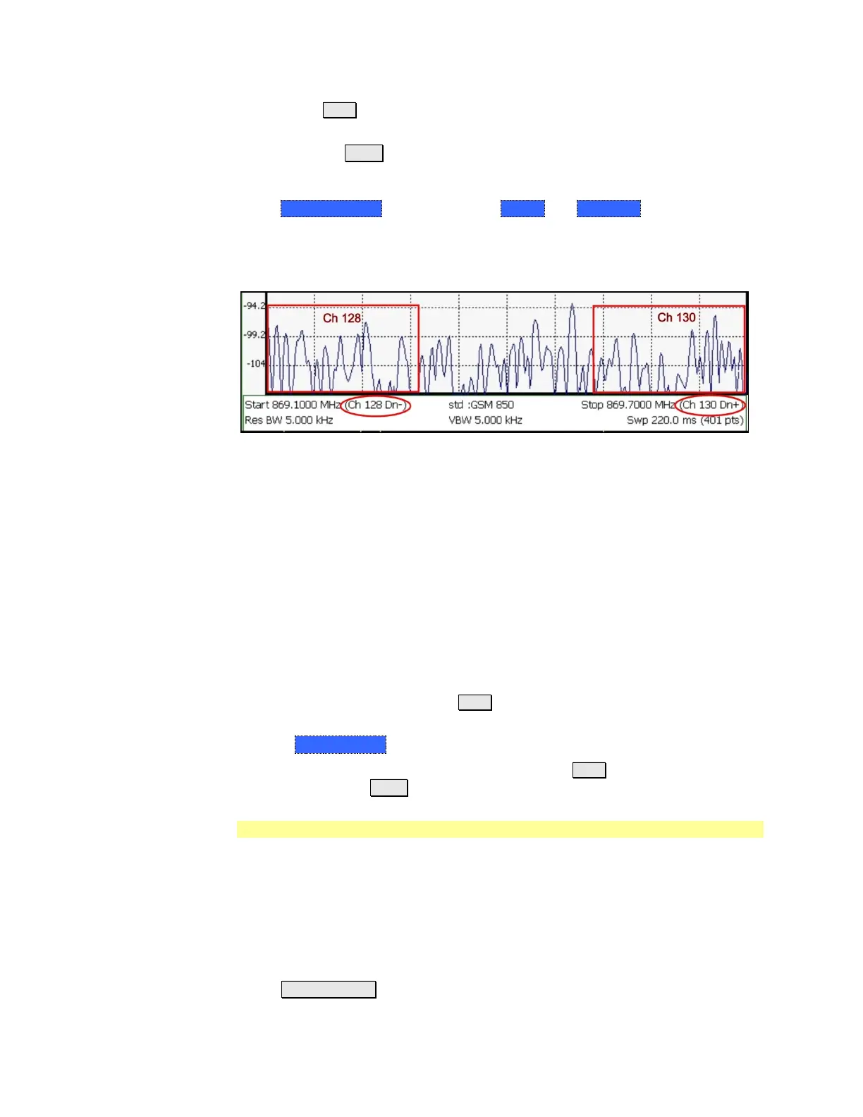
Channel number X-axis annotation
Dn indicates Downlink frequencies.
Up (not shown) indicates Uplink frequencies
(−) indicates that the lowest frequency in the channel (128) is at the left edge
of the screen.
(+) indicates that the highest frequency in the channel (130) is at the right edge
of the screen.
When Center Channel or Freq Span is specified, the X-axis shows the Center
Freq (Channel) and Frequency Span.
When Start or Stop Channel is specified, the X-axis shows the Start Freq
(Channel) and Stop Freq (Channel).
Change Channel Step Size (Optional)
This setting allows you to use the ▲|▼ arrows to increment the channel number
by the specified value.
Press Channel Step
Enter a step value using the numeric keypad, the ▲|▼ arrows, or the rotary
knob. Then press Enter.
Scale and Units
Adjust the Y-axis scale to see the relevant portions of the data trace.
The Y-axis is divided into 10 graticules. A Reference Level is shown on the screen
as a solid horizontal bar that can be placed at any graticule.
When RF Attenuation set to Auto, the RF Attenuation is coupled to Reference
Level.
How to set Scale
Press Scale / Amptd. Then choose from the following:
 Loading...


