44 FieldFox User’s Guide
o Center and Span frequencies - Specify the center frequency and span of
frequencies (half on either side of center).
Follow each by entering a value using the numeric keypad, the ▲|▼ arrows, or
the rotary knob.
After using the ▲|▼ arrows or the rotary knob, press Enter. The increment
setting of the arrows is based on the current span and can NOT be changed in
NA Mode.
After using the keypad, select a multiplier key. Learn about multiplier
abbreviations on page 19.
Scale Settings
Adjust the Y-axis scale to see the relevant portions of the data trace. The Y-axis is
divided into 10 graticules.
This setting can be changed at any time without affecting calibration accuracy.
How to set Scale
Press Scale / Amptd.
Then choose from the following methods:
1. Autoscale Automatically adjusts the Y-axis to comfortably fit the Min and
Max amplitude of the trace on the screen.
2. Autoscale All Autoscales all of the traces on the screen, useful only for
multi-trace configurations.
3. Set Scale, Reference Level, and Reference Position
o Scale Manually enter a scale per division to view specific areas of the trace.
o Ref Level Manually set the value of the reference line. Enter a negative
value by pressing Run/Hold (+/-) either before or after typing a value.
o Ref Position Manually set the position of the reference line. Values must be
between 0 (TOP line) and 10 (BOTTOM line)
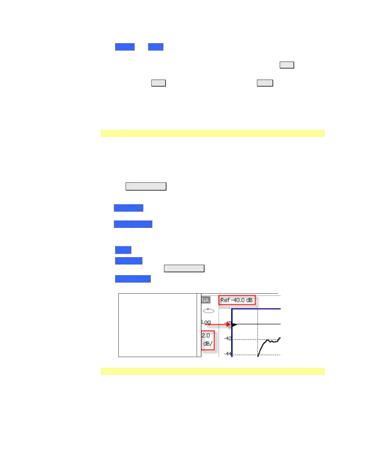
Scale annotation on the
FieldFox screen
· Reference Line = red arrow
· Ref Level = –40 dB
· Ref Position = 1
· Scale = 2 dB per division
Electrical Delay
Electrical delay is a mathematical function that simulates a variable length of
lossless transmission line. Use the electrical delay feature to compensate for the
linear phase shift through a device and view only the deviation from linear phase
of the device.
You can set the electrical delay independently for each measurement trace. To
apply an electrical delay to all measurement traces, use Port Extensions. Learn
how on page 50.
 Loading...


