4. Configuration
110
Device Configuration – Configuration via Direct Representation (%Q)
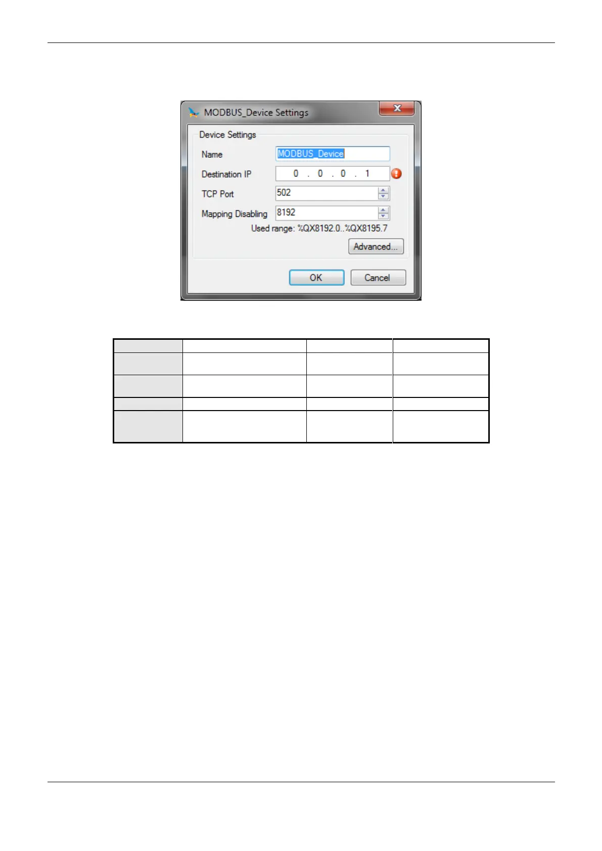
The configuration of client devices, displayed in Figure 4-34, includes the following parameters:
Figure 4-34. Configuring MODBUS Client
Identifier, according to
IEC 61131-3
1.0.0.1 to
223.255.255.255
Initial address used to disable
MODBUS relations
Any address of the %Q
area, limited by the
CPU model.
Table 4-76. Configuration of Client Devices
Notes:
Name: this field is the identifier of the device, which is checked according to IEC 61131-3, i.e. it
does not allow spaces, special characters and starting with numeral character. It is limited to 24
characters.
TCP Port: if there are multiple instances of the protocol added in a single Ethernet interface,
different TCP ports must be selected for each instance. Some TCP ports, among the possibilities
mentioned above, are reserved and therefore cannot be used. They are: 80, 8080, 1217, 1740, 1741,
1742,1743 and 11740.
Mapping Disabling: composed of 32 bits, it is used to disable, individually, the 32 MODBUS
relations configured in device mappings space. The relation is disabled when the corresponding bit is
equal to 1, otherwise, the mapping is enabled. This field is limited by the size of output variables
addressable memory (% Q) at CPU, which can be found in chapter Technical Description - Specific
Features.
Default Value: factory default cannot be set for the Disabling of Mappings field, since the creation
of a protocol instance can be made at any moment within the application development. The
MasterTool IEC XE software itself allocate a value from the range of direct representation output
variables (%Q), still unused.
Communication Time-out: the settings present on the button "Advanced ..." on the TCP connection,
are described in the notes of the section Device Configuration – MODBUS Master Protocol
Configuration by Symbolic Mapping.
 Loading...