4. Configuration
109
Add and configure devices by setting address, direct representation variables (%Q) to disable the
relations and communication port.
Add and configure MODBUS relations, specifying the data type and MODBUS function, time-
outs, direct representation variables (%Q) to receive diagnoses of the relation and other to
receive/write the data, amount of data to be reported and polling of the relation.
The descriptions of each configuration are listed below in this chapter.
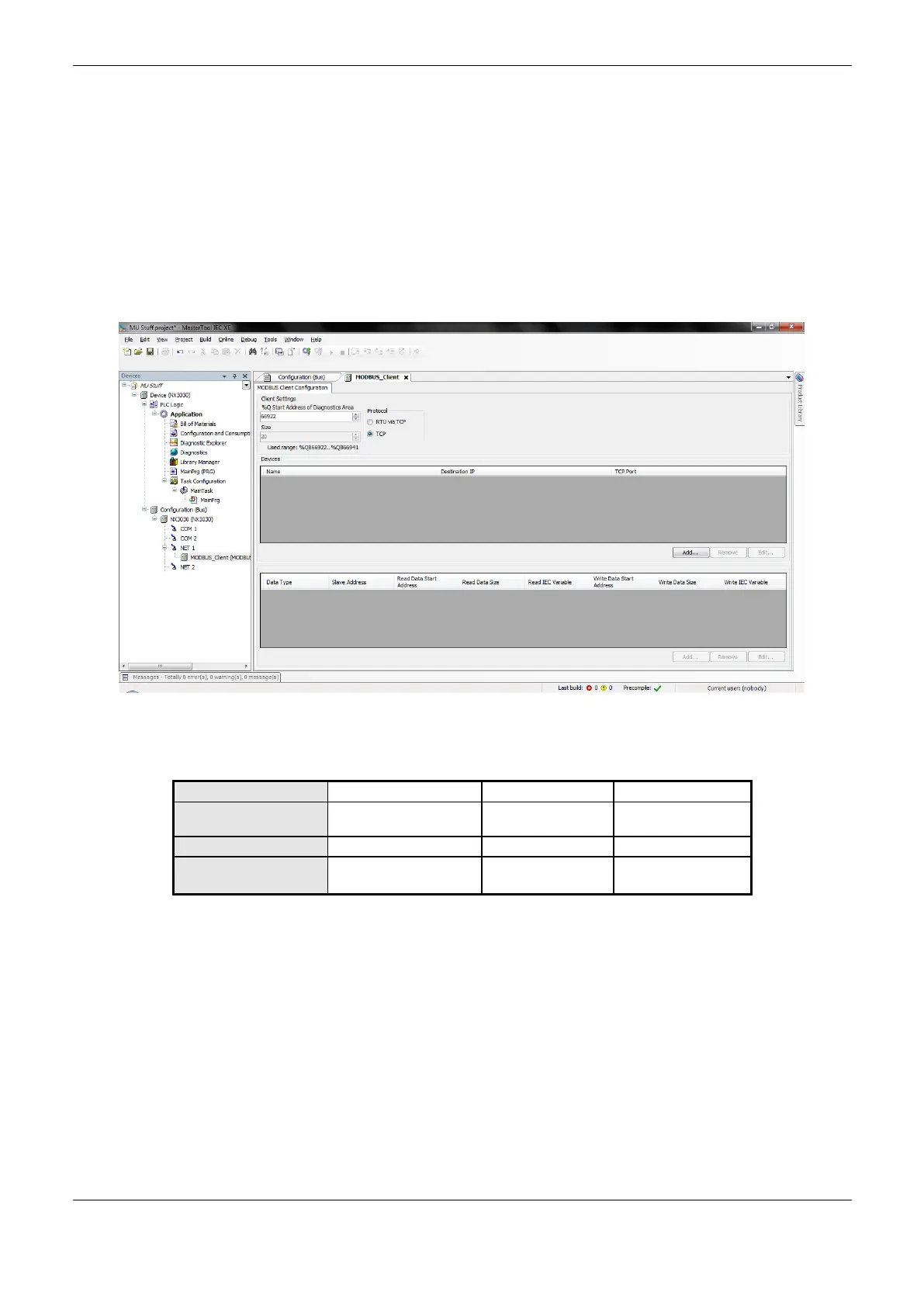
General parameters of MODBUS Protocol Client-configuration for Direct Representation (% Q)
The General parameters, found on the home screen of MODBUS protocol configuration (Figure
4-33), are defined below.
Figure 4-33. MODBUS Client Setup Screen
Protocol selection and direct representation variables (%Q) for diagnostics:
%Q Start Address of
Diagnostics Area
Initial address of the
diagnostic variables
Table 4-75. Protocol selection and direct representation variables for diagnostics
Notes:
%Q Start Address of Diagnostics Area: this field is limited by the size of output variables
addressable memory (%Q) at CPU, which can be found in chapter Technical Description.
Default Value: the default value cannot be defined for the Initial Address of Diagnostics in %Q field
since the creation of a protocol instance can be made at any moment within the application
development. The MasterTool IEC XE software itself allocate a value from the range of direct
representation output variables (%Q), still unused.
The diagnostics and MODBUS commands are described in Table 4-66.
 Loading...