Appendix
IMAGE INTENSIFIERS
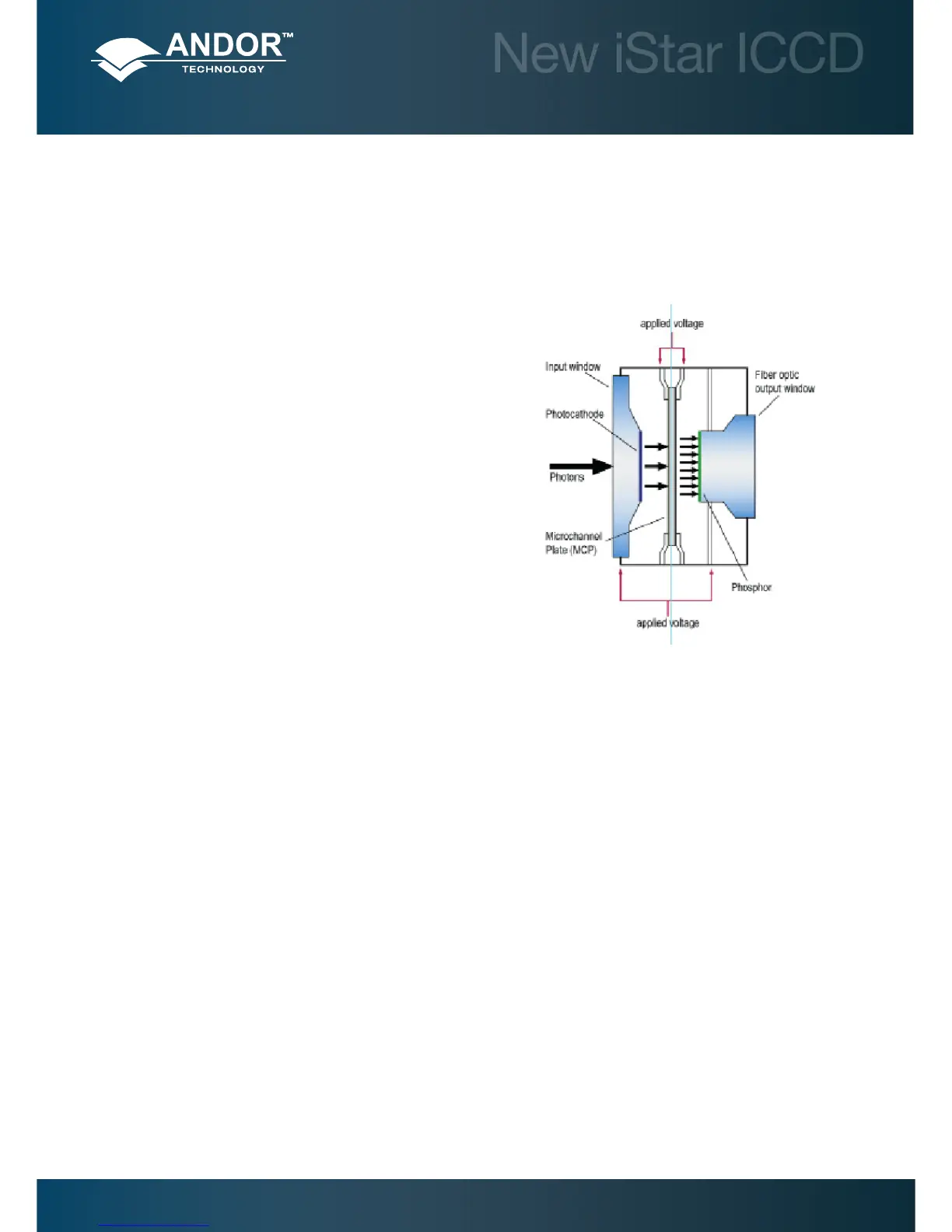
An Image intensier is an evacuated, proximity-focus device that amplies the intensity of an incoming signal. The
device is small, typically 1-2 inches in diameter and 1 inch thick. As well as amplifying incoming signal, an image
intensier can rapidly be switched on and off, allowing it to be used as a very fast optical shutter in the nanosecond time
regime. The image intensier used in the system can either be of 2nd generation (‘Gen 2’) or 3rd generation (‘Gen 3’).
There are three major elements in an image intensier :
• Thephotocathode
• TheMicro-ChannelPlate(MCP)
• TheoutputPhosphorscreen
PHOTOCATHODES AND WINDOWS
The photocathode is coated on the inside surface of an input window, typically made of silica, MgF2, Borosilicate glass
of bre-optic plate. The input window typically set the lower detection limit, while the photocathode set the upper
detection wavelength.
When an incoming photon strikes the photocathode, a photoelectron may be emitted, depending on the QE of the
photocathode. This photoelectron is drawn across a small gap towards the MCP by an electric eld.
‘Gen 2’ refers to multi-alkali based photocathodes that present a wide wavelength coverage from UV up to ~ 900 nm,
with moderate peak QE up to ~25-30%. The lower detection limited is set by the photocathode substrate, typically Silica
of Magnesium Fluoride (MgF2). These photocathode are quite resistive, and require a metallic underlay (full or grid-type)
to achieve nanosecond gating times (at the expense of a few percent QE).
‘Gen 3’ refers to Gallium-Arsenide (GaAs) – based photocathodes. These are typically deposited on glass - which set the
lowest detection limit at ~ 350 nm, and are sensitive up to ~900 nm. They present peak QE up to 50%.
Note: Please refer to sections 2.5 and 2.6 for further details on image intensiers options.
Gating - The voltage on the photocathode in relation to the input of the MCP can be rapidly toggled between 2 levels. If
the voltage of the photocathode is made positive relative to the input of the MCP, then the photoelectrons will not have
sufcient energy to leave the photocathode and the image intensier will effectively be OFF.
By switching the voltage the intensier can be turned ON and OFF. This process is referred to as “Gating”. Gating
periods in the nanosecond scale (billionth of a second) can be readily achieved, making the image intensier, one of the
fastest optical shutters available.