Pre-Acquisition Setup - Image Intensier
5.4 - IMAGE INTENSIFIER SETTINGS
This section details the different image intensier modes of operation relative to ‘gating’ and signal amplication.
5.4.1 - Gate Modes
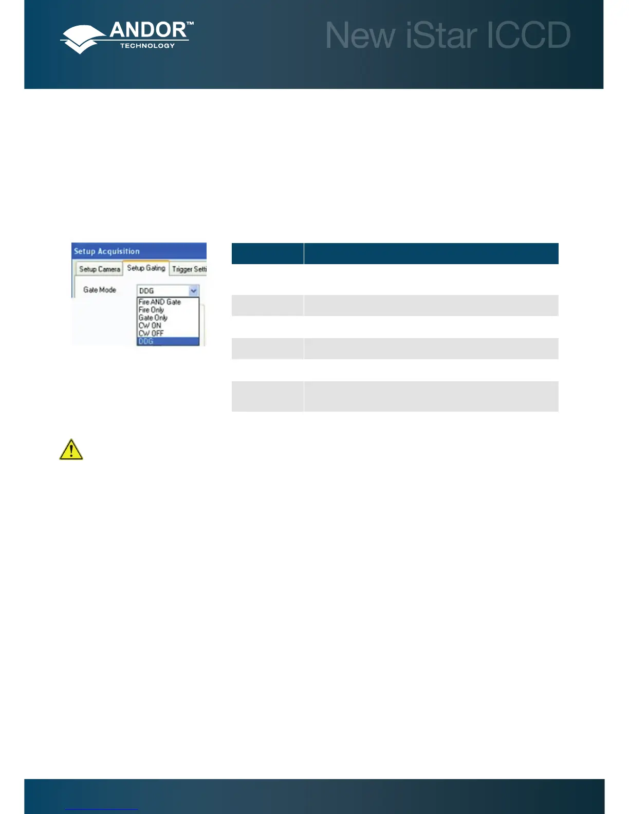
In the Setup Acquisition interface, under Setup Gating tab, a drop-down menu allows the user to select the gate mode
used for data acquisition. Valid options are:
Note: For direct gate input, the maximum safe levels are -0.5 to +5.75 V. The input impedance is 50 Ω
termination to ground. The minimum high logic level is 1.7 V and maximum low logic level is 0.8 V.
5.4.2 - Using Gate Monitor
The gate monitor connection, on the side of the main block of the New iStar, enables the user to monitor the temporal
position of the photocathode switching On (negative spike) and Off (positive spike). A cable is supplied with the New
iStar, which has a BNC connector on one end for attaching to an oscilloscope.
When Intelligate (see section 5.4.5) is selected an additional gate monitor spike precedes the spike from the
photocathode. This spike corresponds to the MCP switching on.
User should set the oscilloscope to trigger on the steepest part of Output A, typically to ½ of the peak amplitude. The
Fire pulse may also be used but its jitter performance with respect to the gate pulse will not be as good.
The plots on the next page show the preferred oscilloscope settings for working with short and long gate widths.
GATE MODE DESCRIPTION
Fire and Gate Photocathode is switched on only when both the Fire & Direct Gate input
are high.
Fire only Photocathode is switched on only when the Fire pulse is high.
Gate only Photocathode is switched on only when the Direct Gate input is high.
CW On The photocathode is continuously in the ON state
CW Off The photocathode is continuously in the OFF state.
DDG The photocathode is switched on only when the Gate pulse from the
DDG is high.