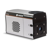
Installing the New iStar
Prior to commencing installation, user should refer to the safety and warning information at the beginning of this manual.
3.1 - MECHANICAL CONNECTION TO THE NEW ISTAR
3.1.1 - Attaching to a Spectrograph
The New iStar can be easily connected to Andor’s Shamrock spectrograph. If the New iStar and Andor’s spectrograph
have been ordered at the same time, the system will arrive already pre-aligned and integrated. Outside this scenario -
including matching the New iStar to a third-party spectrograph - the following generic instructions should be followed:
1. Bolt the detector to the camera mounting ange, ensuring that the head is correctly orientated and that the
appropriate O-ring is inserted at the front of the detector head.
2. Attach the camera mounting ange to the spectrograph, ensuring that the appropriate O-ring is in place
between both detector ange and spectrograph ange.
3. Secure all four attachment screws so that the detector head, the anges and the spectrograph are tted together
securely in order to allow correct grounding through the connector cable. Good grounding maintains the low
noise performance of the detector, and in severe environments may prevent the instrument from damage.
3.1.2 - Attaching to a Lens System
The Andor New iStar can also be easily connected to a lens system for imaging purposes. Andor local representative
can supply details of the available adaptors for connecting the detector head to various manufacturers’ lenses. The
following general instructions should be followed:
1. When attaching the New iStar to a lens adaptor (C-Mount or F-Mount for example), ensure rst that the
adpater is correctly orientated and aligned. Ensure that the appropriate O-ring is inserted between the camera
front plate and the lens adaptor plate. In the case of the C-Mount, place the side of the adaptor that is ush
with the brass insert towards the New iStar front plate. Ensure that all four attachment screws are secured to
the adaptor.
2. Attach the appropriate lens into the brass insert (C-Mount) or bayonnet interface (F-Mount) of the lens adaptor.
3.1.3 - Attaching to Nounting Posts
THREE ¼ -20 UNC THREADED HOLES ARE LOCATED ON THE UNDERSIDE OF THE UNIT. DRAWING IN SECTION 2.2
PROVIDES PRECISE LOCATION OF THESE MOUNTING HOLES.
SECTION 3 - INSTALLING THE NEW ISTAR

 Loading...