Pre-Acquisition Setup - CCD
5.5 - TRIGGERING MODES
THE TRIGGERING MODES ARE SELECTED FROM A DROP-DOWN LIST ON THE SETUP ACQUISITION DIALOG BOX.
5.5.1 - Internal Trigger
Camera acts as a timing master for any external device, and also triggers both CCD and intensier simultaneously. The
camera determines the exact time when an exposure happens, based on the acquisition settings entered by the user.
To control an external device in time (e.g. a laser) output A, B or C can from the DDG should be used (see section 6 for
details on setup).
5.5.2 - External Trigger
Camera waits for a trigger from an external device to perform the acquisition sequence, hence acting as a timing slave;
both CCD and intensiers are triggered simultaneously. Once an acquisition has been started, the camera is placed into
a special cleaning cycle called “External Keep Clean Cycle” which ensures that charge build up on the CCD is kept to
a minimum while waiting for the external trigger event. The external keep clean consists of a continuous sequence of
one vertical shift followed by one horizontal shift. Once the External Trigger is received the current keep clean sequence
is completed and the exposure phase initiated. The exact nature of the acquisition will depend on the user settings and
is explained in more detail in a subsequent section. The external trigger is fed via the Ext Trig input on the camera head.
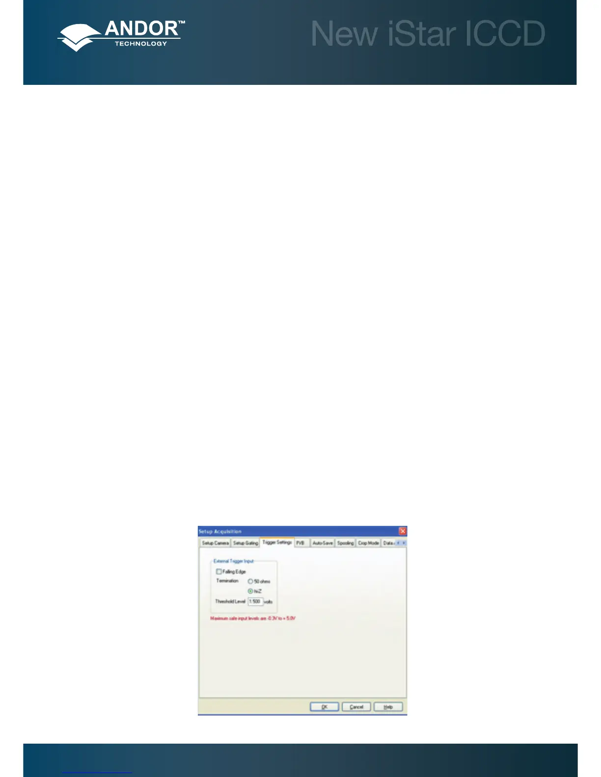
The maximum safe input levels are -0.3 to +5.0 V. The user can congure the following settings under the Trigger
settings tab:
Termination: The input impedance can be change between High Impedance and 50 Ω.
Rising or Falling Edge Triggered: The system can be set to respond to rising edge or falling edge triggers.
Threshold Level: The trigger threshold can be programmed from +0.25 to +3.3 V.
When using external trigger the user may nd it useful to monitor the Arm output at back of the detector head. When the
Arm is high the system will accept external triggers.
For lowest jitter, the user may need to adjust the input impedance and/or trigger threshold to set the trigger level to the
steepest part the input edge, typically 1/3 to 1/2 of the peak amplitude.