5.4.7 - Digital Delay Generator (DDG)
The New iStar’s Digital Delay Generator (DDG) is built directly into the detector head. A trigger source (external trigger or
internal trigger (Fire pulse)) activates the DDG, so that it can control the image intensier for gating applications.
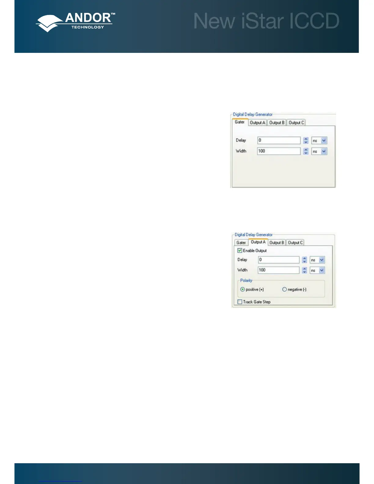
5.4.7.1 - Gater
Gate Delay: The user can introduce a delay to the gate pulse in order to
synchronise the opening of the image intensier with an optical pulse. The
range can be set from 0 to 10 s.
Gate Width: The user can enter the length of time the image intensier is
switched (or gated) On. Optical signal falls on the CCD sensor during this
time. The range can be set from 0 to 10 s.
Resolution: 10 ps.
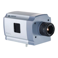
5.4.7.2 - Output A, B & C
The DDG can send out auxiliary output pulses called Output A, Output B, and Output C. These outputs are +5 V
CMOS level with 50 Ω source impedance. They can drive 5 V into a non-terminating load or 2.5 V into 50 Ω load. The
outputs can be used to synchronize triggers for auxiliary equipment, e.g.
lasers, ash lamps or National Instrument™ hardware. It is recommended
that these outputs be use as a trigger sources, rather than the Fire pulse,
since they have better jitter performance with respect to the gate pulse.
Fire pulse is best used as an indication of when the CCD expects to be
exposed to light.
Delay: The user can congure the delay individually for each output - The
range can be set from 0 to 10 s.
Width: The user can congure the width individually for each output - The
range can be set from 2 ns to 10 s.
Resolution: 10 ps.
Polarity: Positive (low-high-low) or negative (high-low-high).
5.4.7.3 - Optical Width
When this option is selected in the Gater tab of the Setup Acquisition interface, the gate width becomes the factory
measured actual optical gate width.
Note: Optical width versus electrical TTL widths is reported individually on the performance sheet of every
New iStar.
Pre-Acquisition Setup - Image Intensier