EasyManua.ls Logo

Andor Technology New iStar User Manual

Andor Technology New iStar
155 pages
To Next Page IconTo Next Page
To Previous Page IconTo Previous Page
Page #66 background imageLoading...
Page #66 background image
Page 66
New iStar ICCD
Pre-Acquisition Setup - CCD
5.3.3.2 - Horizontal Binning
In this conguration, charges from two or more pixels in the serial register are transferred into the output amplier and
read out as one combined data value. Thus the charges from two or more of the horizontal elements are effectively
summed into the output amplier before being readout.
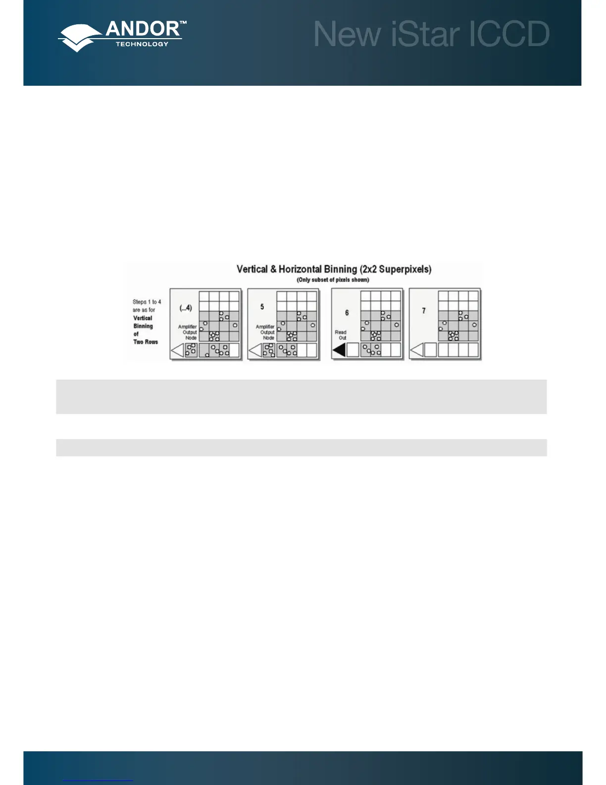
In the example below (where each superpixel is of dimensions 2 x 2 pixels) charges from two rows is rst binned vertically
into the shift register; then charges from two pixels of the shift register are binned horizontally into the output node of the
amplier. The effect of the combined binning processes is a summed charges equating to a 2 x 2 ‘superpixel’.
Since this example initially involves binning charge from two rows, the process begins in the same way as the previous
example (see Steps 1 - 4 of Vertical Binning section).
(...4)
Charges from two rows have already been vertically binned into the shift register. Charges in the shift register are now moved horizontally by one
pixel, so that charges on the endmost pixel of the shift register are moved into the output node of the amplier.
5
Charges in the shift register are again moved horizontally, so that the output node of the amplier now contains charges from two pixels of the
shift register - i.e. the charges have been horizontally binned.
6 The charges in the output node of the amplier are passed to the analog-to-digital converter to be read out.
7
Steps 4 to 6 are repeated until the shift register is empty. The process is repeated from Step 2 (in Vertical Binning section) until the whole frame
is read out.

Table of Contents

Question and Answer IconNeed help?

Do you have a question about the Andor Technology New iStar and is the answer not in the manual?

Andor Technology New iStar Specifications

General IconGeneral
BrandAndor Technology
ModelNew iStar
CategorySecurity Camera
LanguageEnglish

Summary

SECTION 1: ABOUT THE NEW iSTAR

1.6 ELECTRICAL & ENVIRONMENTAL SPECIFICATIONS

Lists the electrical and environmental operating parameters for the camera.

SECTION 2: INTRODUCTION TO THE NEW iSTAR

2.8 COOLING

Explains the cooling methods and performance characteristics of the detector.

SECTION 3: INSTALLING THE NEW iSTAR

3.1 MECHANICAL CONNECTION

Instructions for physically connecting the camera to optical systems like spectrographs or lenses.

3.3 ELECTRICAL CONNECTIONS

Guidelines for making the necessary electrical connections to the camera.

3.4 INSTALLING SOFTWARE AND USB DRIVERS

Step-by-step guide for installing the camera software and USB drivers on a PC.

SECTION 4: SOLIS SOFTWARE OPERATION

4.5 RUN-TIME CONTROL

Details how to control acquisition parameters in real-time using slider controls.

SECTION 5: PRE-ACQUISITION SETUP

5.1 SETTING TEMPERATURE

Explains how to cool the detector for optimal performance and reduced noise.

5.3 CCD SETUP ACQUISITION

Guides the user through configuring CCD acquisition modes and parameters.

5.4 IMAGE INTENSIFIER SETTINGS

Details the settings for controlling the image intensifier's gating and amplification.

5.5 TRIGGERING MODES

Explains the different modes for initiating data acquisition sequences.

SECTION 6: OPERATION: GATING, TRIGGERING & SYNCHRONIZATION

6.1 TRIGGERING: INTERNAL

Describes operation using the internal trigger for timing and synchronization.

6.2 TRIGGERING: EXTERNAL

Explains operation using external triggers for synchronization with other devices.

Related product manuals