The other connection points are as follows:
• USB 2.0: A USB 2.0 compatible cable can be connected between the USB socket and a PC. Optional locking
connection is also available
• I
2
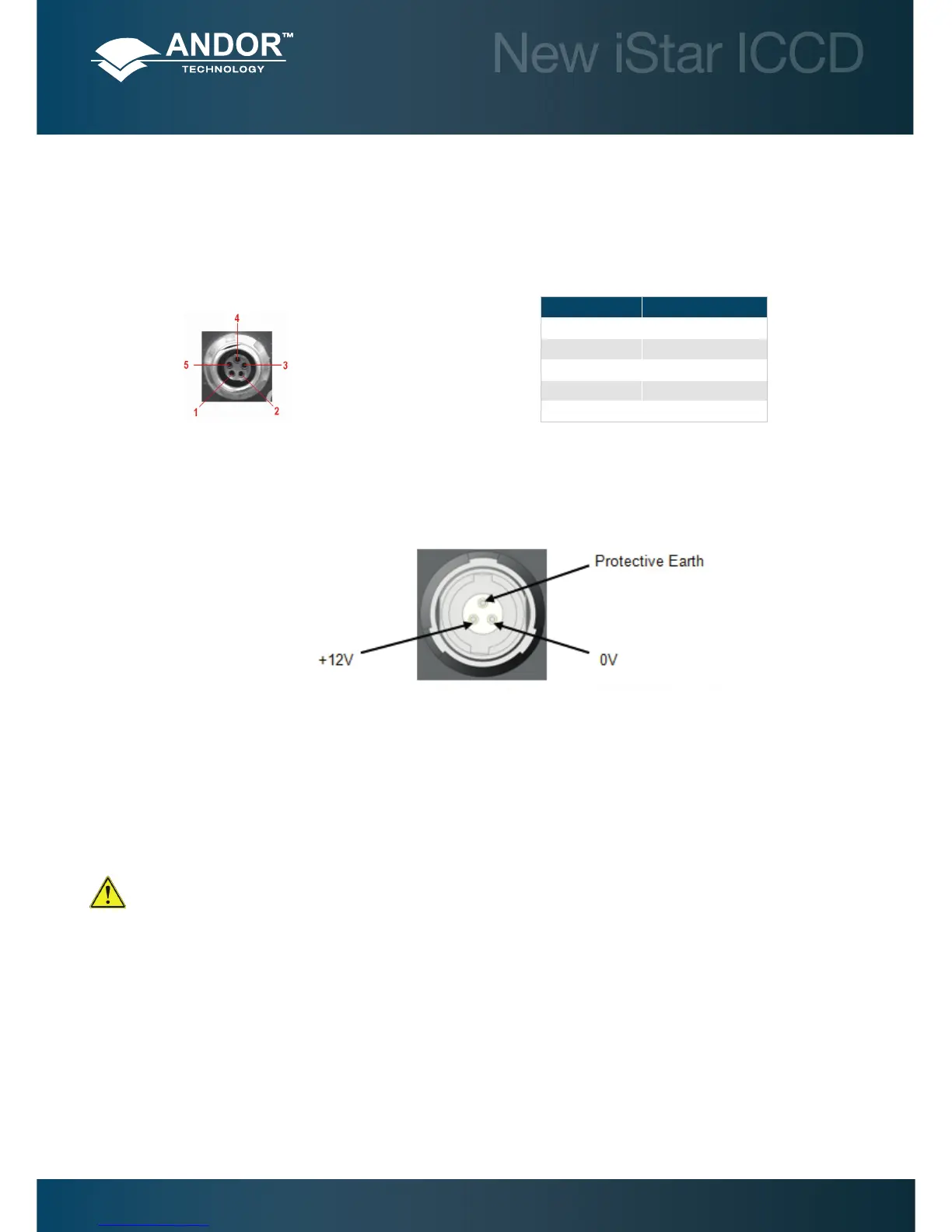
C: The user can communicate with other I
2
C devices by means of the 5-way receptacle (Fischer P/N DBP 102
A 054 – 130) on the rear of the New iStar. The pin-out of this connector is shown below:
Table 3: I
2
C connection (facing in) with pin-outs
• Power: A 3-pin power connector is tted for power connection, with the following pinout:
Figure 6: Power connector pin-outs. Matching cable connector is 3-pin Redel no. PAH.N0.3GL.LC65G
• Earthing stud: Means of providing protective earth connection to camera head when it is not, or cannot be
provided via the 3-pin power connector
Before inserting the power connector, ensure that the orientation is correct. Never forcibly insert the
connector, otherwise damage to the equipment will occur.
Pin Function
1 SHUTTER (TTL)
2 I
2
C CLOCK
3 I
2
C DATA
4 +5 V
5 GROUND
Introduction to the New iStar