Assembly Removal and Replacement, MS202xC 6-17 Replacing Power Monitor PCB Assembly, Option 5 –
MS20xxC MM PN: 10580-00307 Rev. D 6-27
6-17 Replacing Power Monitor PCB Assembly, Option 5 – ND67197
This procedure provides instructions for replacing the Power Monitor PCB Assembly (Option 5) and its related
Detector connector.
Part Number
• ND67197 – Power Monitor PCB Assembly, includes the BNC connector on Flex Board and mounting
hardware.
Procedure
1. Open the case as described in Section 6-16 “Opening the Instrument Case” on page 6-24.
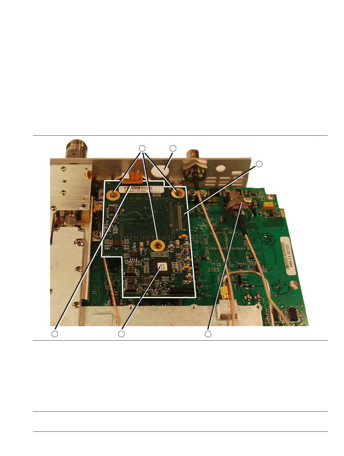
2. Locate the Power Monitor Assembly PCB Option as shown in Figure 6-13.
1. Optional Power Monitor PCB Assembly - Option 5
2. Removable Flex Cable 4-Pin connector between Detector connector (on connector panel) and
Power Monitor PCB.
3. Mounting screws (3 each) (removed in this image)
4. Mounting hole on connector panel for removed Ext. Trig BNC connector.
5. Location of Header and M-M Header Pin Strip under PCB between Power Monitor PCB and
VNA Assembly PCB
6. Ext. Trig. BNC connector that must be removed to access a VNA PCB Assembly mounting screw (not shown).
Figure 6-13. Power Monitor PCB Assembly - Option 5

 Loading...


