Assembly Removal and Replacement, MS203xC 7-21 Removing MS203xC Main PCB Assembly
MS20xxC MM PN: 10580-00307 Rev. D 7-55
Procedure
1. Place the instrument face up on a protected work surface oriented with the top Connector Panel away
from you.
2. Remove the Battery Door and the Battery.
Opening the Case and Remove the VNA PCB:
1. Open the case as described in Section 7-16 “Opening the Instrument Case” on page 7-26.
Disconnecting GPS Antenna Cable:
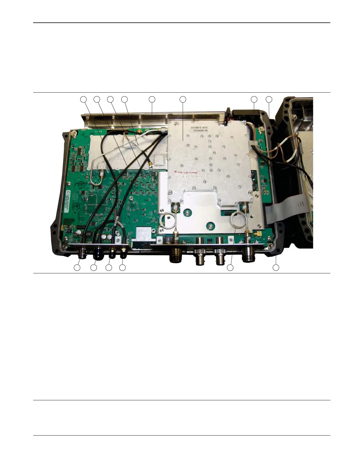
1. External Trigger cable (to MB J3202)
2. External Reference cable (to SPA J6000)
3. 10 MHz Reference Out cable (to SPA J6001)
4. 26 MHz VNA Reference cable (to MB J2201)
5. Battery Compartment
6. RF Module
7. Cable bundle between VNA PCB Assembly and SPA PCB (4 cables)
8. Ribbon cable from MB J3000 to SPA J5001
9. Semi-Rigid cable to VNA Port
10.GPS connector
11.10 MHz REF OUT connector
12.EXT TRIG connector
13.EXT REF connector
Figure 7-25. VNA Assembly – Connected Within Front Case, MS2036C Shown

 Loading...


