Assembly Removal and Replacement, MS202xC 6-8 Internal Anatomy of the VNA Master MS2026C
MS20xxC MM PN: 10580-00307 Rev. D 6-7
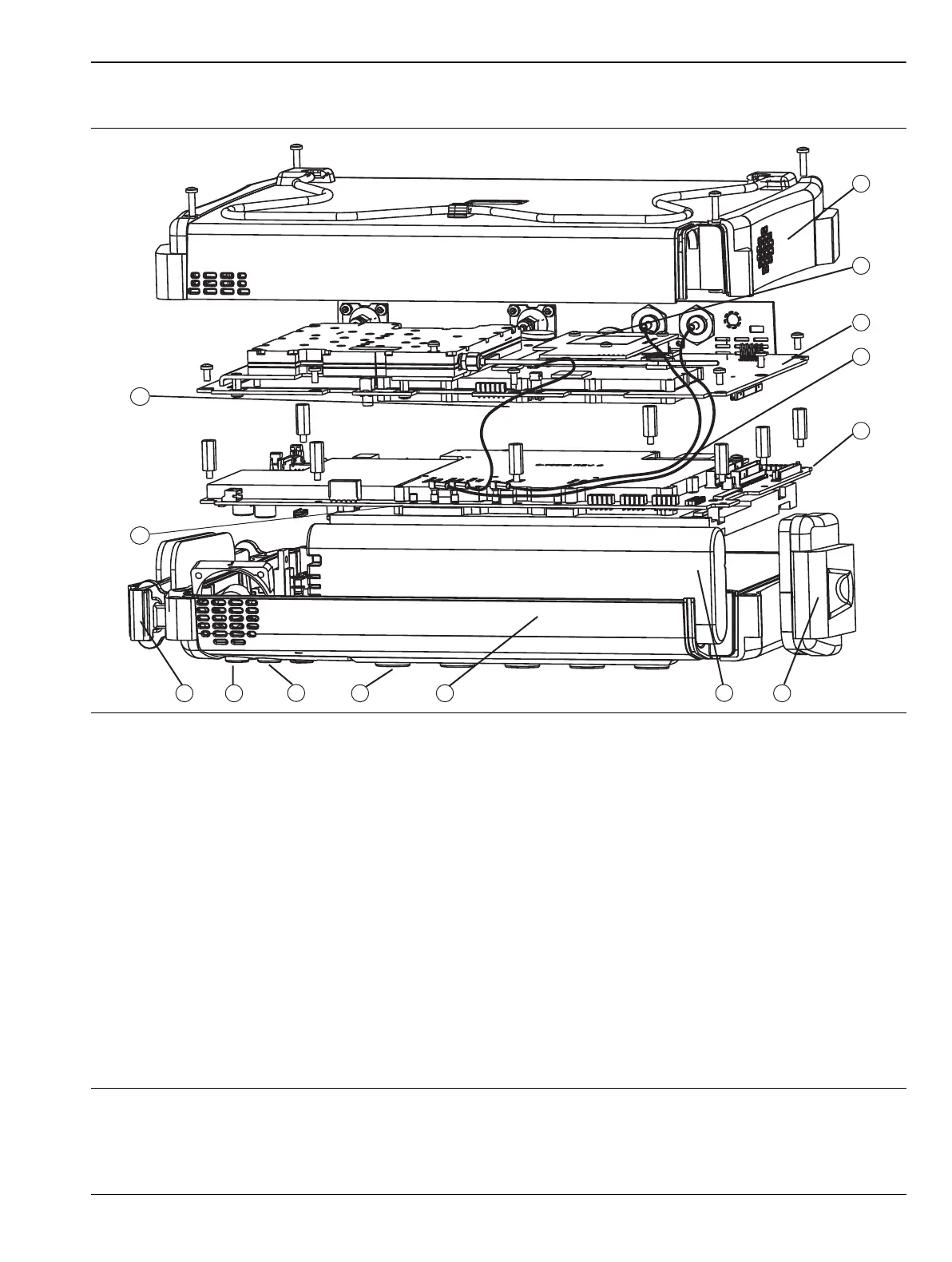
MS2026C View from Bottom
1. Case Back
2. Power Monitor Option 5 PCB Assembly (behind connector strip)
3. VNA PCB Assembly with N(f) Connectors
4. GPS Module Option 31 PCB Assembly
5. Main PCB Assembly (Mother Board)
6. Battery Door
7. Battery
8. Case Front
9. Main Menu Keypad (mounted on Case Front)
10.Numeric Keypad (mounted on Case Front)
11.Rotary Knob and Rotary Encoder (mounted on Case Front)
12.Hand Strap (mounted on Case Front)
13.LCD Display (mounted on Main PCB Assembly)
14.VNA cable to J2201 on Main PCB Assembly (Mother Board)
Figure 6-5. VNA Master MS2026C Major Assemblies – Viewed from Bottom
 Loading...


