7-9 Internal Anatomy of the VNA Master MS2037C and MS2038C Assembly Removal and Replacement,
7-8 PN: 10580-00307 Rev. D MS20xxC MM
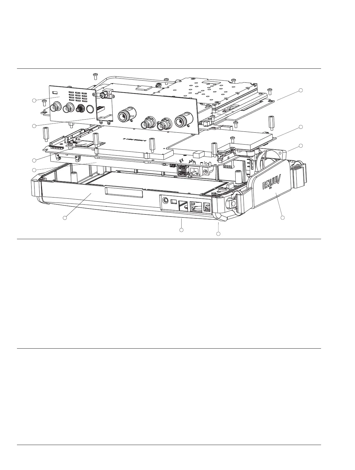
7-9 Internal Anatomy of the VNA Master MS2037C and MS2038C
MS2037C and MS2038C View from Top Connector Panel
1. VNA PCB Assembly with N(f) Connectors
2. Main PCB Assembly
3. Cooling Fan Assembly
4. Hand Strap (mounted on Case Front)
5. Rotary Knob and Rotary Encoder (mounted on Case Front)
6. Main Keypad (mounted on Case Front)
7. Case Front
8. LCD Display (mounted on Main PCB Assembly)
9. GPS Module Option 31 PCB Assembly
10.Location of N(f) Connector for Spectrum Analyzer
11.Connector Panel
Figure 7-6. VNA Master MS2037C and MS2038C Major Assemblies – Viewed from Top Connector Panel

 Loading...


