7-18 Replacing VNA PCB Assembly Assembly Removal and Replacement, MS203xC
7-38 PN: 10580-00307 Rev. D MS20xxC MM
Procedure
Opening the Case:
1. Open the case as described in Section 7-16 “Opening the Instrument Case” on page 7-26.
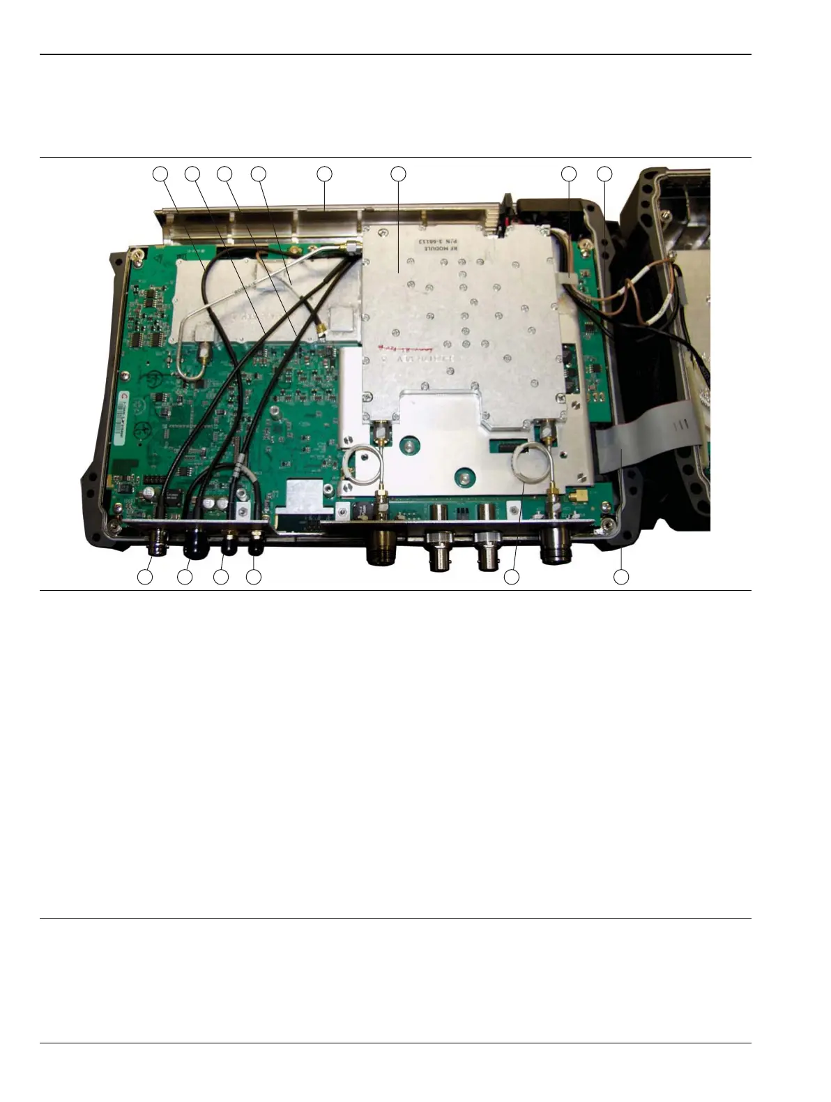
Figure 7-18 shows model MS2036C. All steps to remove and replace the VNA PCB Assembly are the same for
MS2036C, MS2037C and MS2038C instruments. In model MS2037C and MS2038C, the microwave module
replaces the 2 semi-rigid cables shown as item 10. Refer also to the microwave module, item 15 in Figure 7-7
on page 7-9.
1. External Trigger cable (to MB J3202)
2. External Reference cable (to SPA J6000)
3. 10 MHz Reference Out cable (to SPA J6001)
4. 26 MHz VNA Reference cable (to MB J2201)
5. Battery Compartment
6. RF Module
7. Cable clip for 4 RF cables to SPA PCB
8. Cable bundle between VNA PCB Assembly and SPA PCB (4 cables)
9. Ribbon cable from MB J3000 to SPA J5001
10.Semi-Rigid cable to VNA Port
11.GPS Antenna SMA connector
12.10 MHz REF OUT connector
13.EXT TRIG connector
14.EXT REF connector
Figure 7-18. VNA Assembly – Connected Within Front Case, MS2036C Shown
 Loading...


