Assembly Removal and Replacement, MS203xC 7-8 Internal Anatomy of the VNA Master MS2036C
MS20xxC MM PN: 10580-00307 Rev. D 7-7
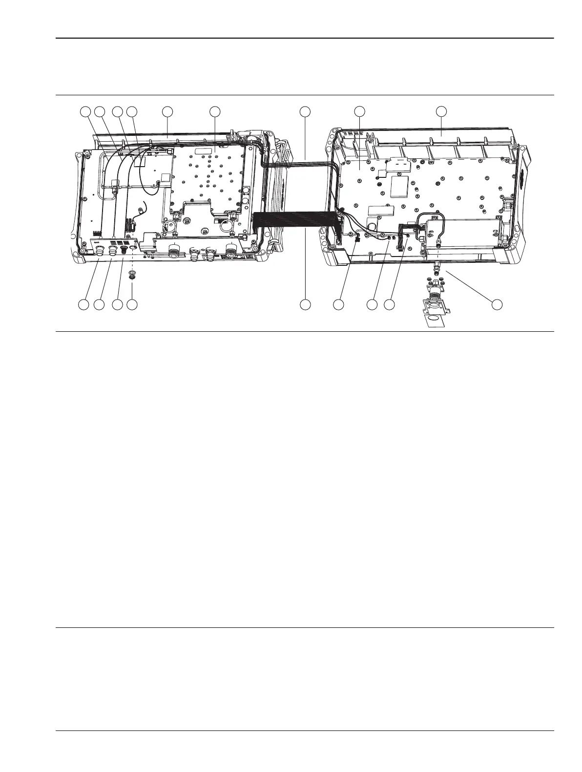
MS2036C Connections Front to Back
View for Joining Front and Back Case Assemblies
1. BNC Cable Assembly, from External Reference Connector to Connector J6000 on SPA PCB
2. BNC Cable Assembly, from External Trigger Connector to Connector J3202 of Mother Board LCD Assembly
3. Cable, from 10 MHz Reference Out SMA Connector to Connector J6001 on SPA PCB
4. MCX Cable Assembly, Mother Board J2201 (26 MHz Out) to top shield of VNA Module at J7002
5. Front Case Assembly, with Mother Board Assembly and VNA Board Assembly
6. RF Module of VNA Board Assembly
7. 4 Cables Between Case Front and Case Back
8. SPA Board Assembly in Case Back
9. Back Case Assembly, with SPA Board Assembly
10.Spectrum Analyzer RF In Connector Assembly
11.MMCX Connector J4004, Receives Cable from J3203 (14.0 MHz IF) of Mother Board
12.MMCX Connector J6002, Receives Cable from J2200 (100 MHz In) of Mother Board
13.MMCX Connector J6000, Receives BNC Cable from External Reference Connector in Front Case Assembly
14.SMA Cable Assembly (ribbon cable) from Mother Board Connector J3000 to Connector J6001 of SPA Board
15.GPS Antenna Location (with Option 31)
16.10 MHz Reference Out Connector (SMA)
17.External Trigger Connector (BNC)
18.External Reference Connector (BNC)
Figure 7-5. VNA Master MS2036C Major Assemblies – Connections Front to Back
7
8
6
1
9
5
14
13
12 101115161718
2 3
4

 Loading...


