Assembly Removal and Replacement, MS203xC 7-25 Installing Main PCB and Reassembling Instrument
MS20xxC MM PN: 10580-00307 Rev. D 7-67
7-25 Installing Main PCB and Reassembling Instrument
This procedure is written with the assumption that any required assemblies have been replaced and installed
on the Main PCB Assembly.
Procedure
Installing the Main PCB Components:
1. If not already done, then install the LCD Display on the Main PCB as described in
Section 7-23 “Replacing LCD Display – 3-15-154” on page 7-64.
Installing the Clear Plastic LCD Protector:
2. If required, but not already done, then install the LCD Protector as described in Section 7-24 “Replacing
Clear Plastic LCD Protector – 3-61368” on page 7-66.
3. If not already done, then clean the inner surface of the Protector with compressed air and LCD
compatible wipes, leaving the outer protective film in place, and place the Protector into the Case Front,
with the “lip” towards the inside of the case.
Installing the Main PCB:
4. The connectors (External Power Input, LAN, USB, and Headset Jack) of the Main PCB will protrude into
the Case Front. Holding the standoff (item 7 in Figure 7-33), insert that connector edge of the Main PCB
first into the case.
a. Rest the edge of the Main PCB on the screw pads and apply a slight pressure to the Main PCB
toward the top of the case by pressing on a shield. If the Main Keypad is not yet installed in the
Case Front, then skip to Step 5. If the Main Keypad is already installed in the Case Front, then
continue with the following sub steps:
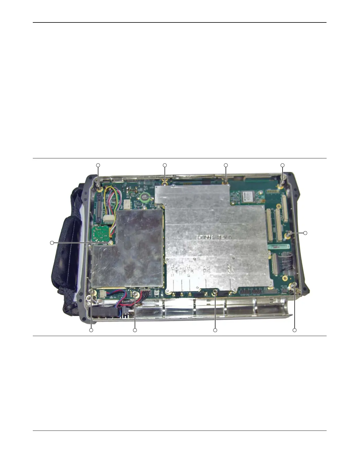
Figure 7-33. Main PCB (Mother Board) in Case – Standoffs and Screws

 Loading...


