6-9 Internal Anatomy of the VNA Master MS2027C and MS2028C Assembly Removal and Replacement,
6-8 PN: 10580-00307 Rev. D MS20xxC MM
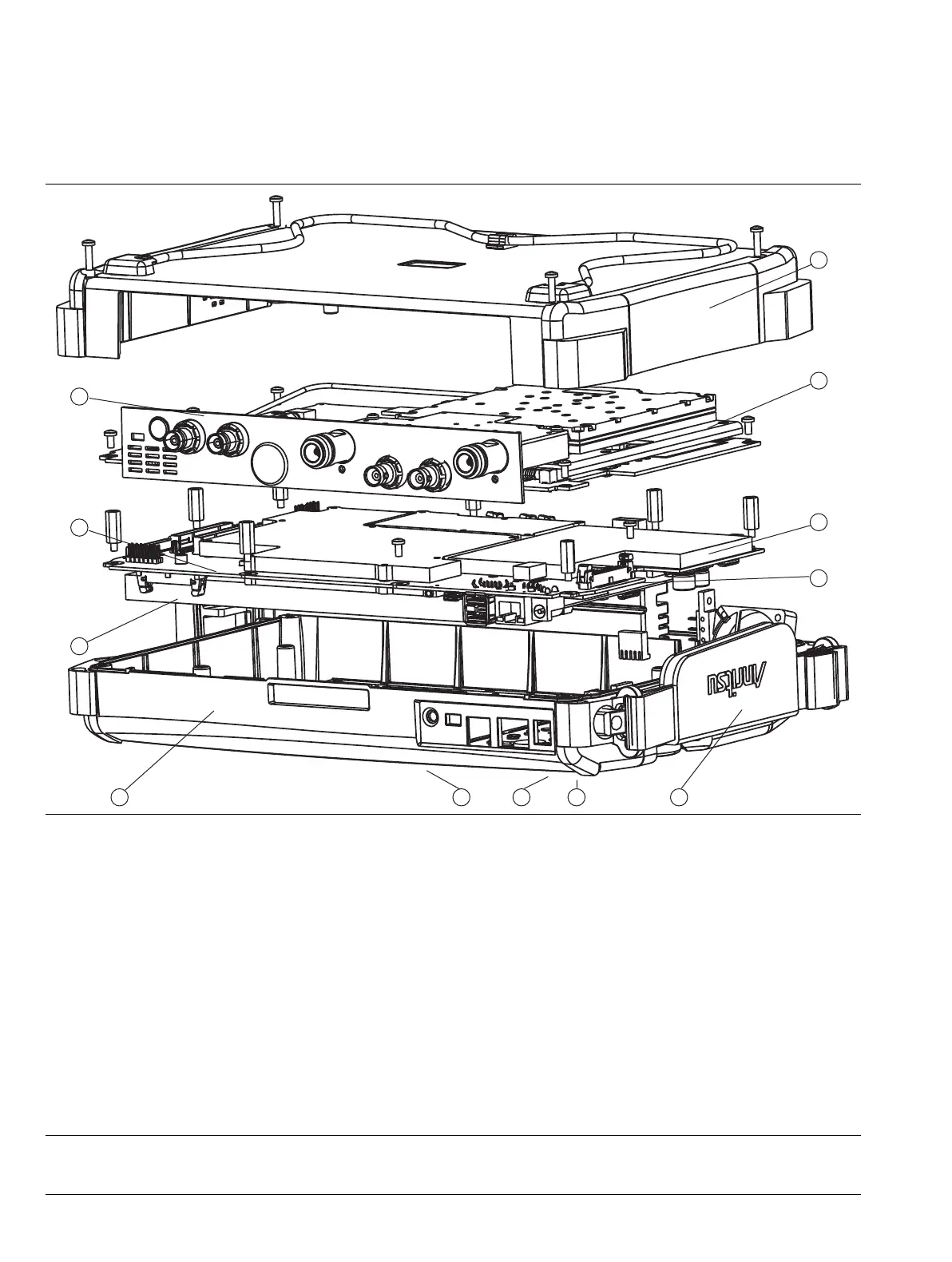
6-9 Internal Anatomy of the VNA Master MS2027C and MS2028C
MS2027C and MS2028C View from Top Connector Strip
1. Case Back and Mounting Screws
2. VNA PCB Assembly with N(f) Connectors and Mounting Screws
3. Main PCB Assembly with Hex (m-f) Standoffs
4. LCD Backlight Cable Location (on Main PCB Assembly)
5. Hand Strap (mounted on Case Front)
6. Rotary Knob and Rotary Encoder (mounted on Case Front)
7. Main Keypad (mounted on Case Front)
8. Main Menu Keypad (mounted on Case Front)
9. Case Front
10.LCD Display (mounted on Main PCB Assembly)
11.GPS Module Option 31 PCB Assembly
12.Power Monitor Option 5 PCB Assembly (behind connector strip)
Figure 6-6. VNA Master MS2027C and MS2028C Major Assemblies – Viewed from Top Connector Strip

 Loading...


