7-17 Replacing SPA Module Assembly Assembly Removal and Replacement, MS203xC
7-32 PN: 10580-00307 Rev. D MS20xxC MM
Procedure
Opening the Case:
1. Open the case as described in Section 7-16 “Opening the Instrument Case” on page 7-26.
Removing Cables and Ext Trig Input BNC:
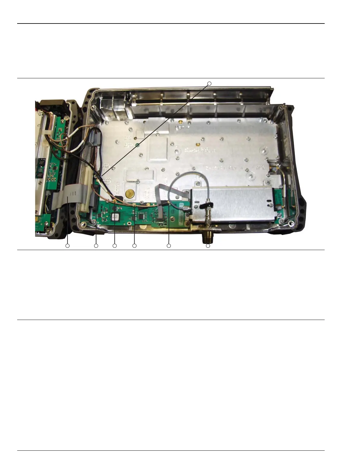
2. Use Figure 7-15 to identify the cable connections for removal and replacement of the SPA PCB.
3. Press downward and then outward to open the cable clip (item 13 in Figure 7-16) that holds the 4 single
cables from the Mother Board and VNA Assembly.
4. Use needle-nose pliers to remove the MCX RF coaxial cables from J6001, J6000, J6002, and J4004.
5. Pry open the cable clamp that holds the ribbon cable connector (J5001, item 11 in Figure 7-16), work the
connector loose, and remove the cable.
This cable clamp is shown closed on the ribbon cable in Figure 7-15 and is shown open and empty in
Figure 7-16. Note the end that is hinged and the shape of the open end.
1. Connector J6001 (adjacent to ribbon cable J5001), 10 MHz Ref Out (cable connects to Ref Out 10 MHz SMA)
2. SPA RF In connector (Type N or Type K with Option 11)
3. Connector J4004, 140 MHz IF (cable connects to J3203 on Mother Board)
4. Connector J6002, 100 MHz MB (cable connects to J2200 on Mother Board)
5. Connector J6000, Ext Ref (cable connects to Ext Ref BNC on top connector panel)
6. Connector J5001, main connection from SPA PCB to Mother Board at J3000
7. Ribbon Cable, SPA PCB (J5001) to Mother Board (J3000)
Figure 7-15. SPA PCB Connections to Top Case Assembly
 Loading...


