Assembly Removal and Replacement, MS203xC 7-17 Replacing SPA Module Assembly
MS20xxC MM PN: 10580-00307 Rev. D 7-33
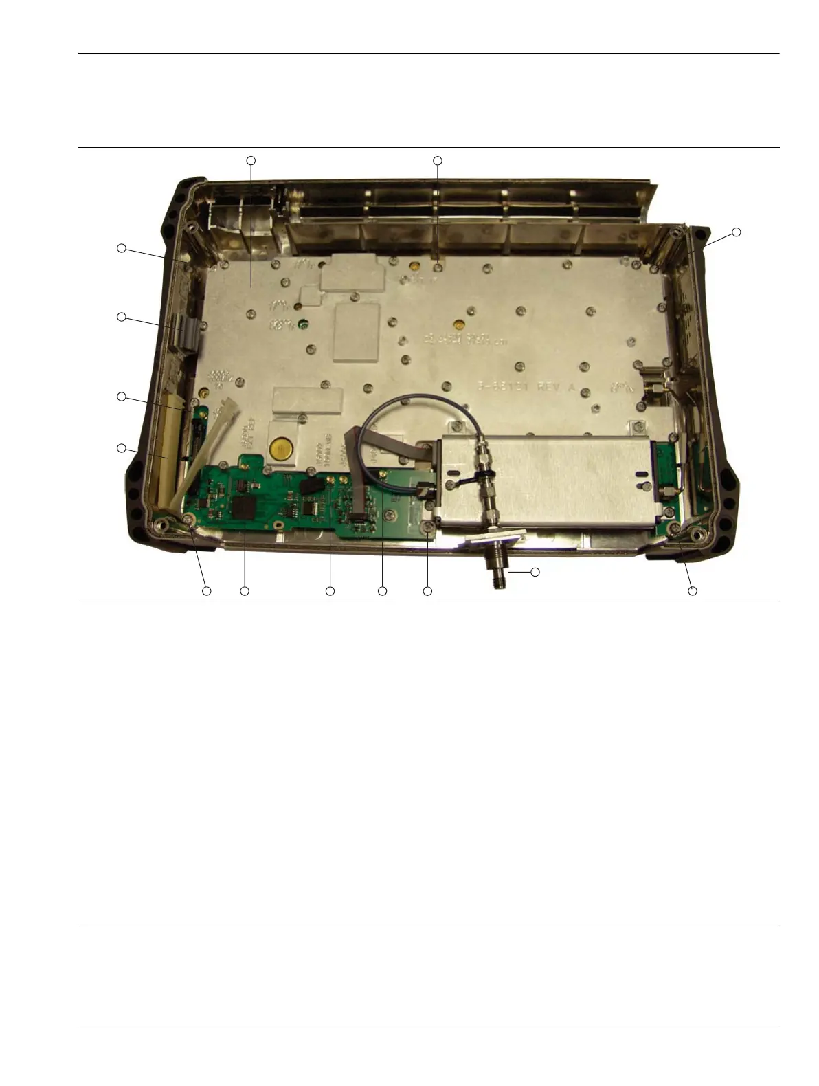
Identifying SPA PCB Mounting Screws:
6. Using Figure 7-16, identify the locations of the six (6) Phillips-head mounting screws that hold the SPA
PCB in place.
Removing the SPA PCB:
7. Using a Phillips-head screwdriver, remove the six (6) screws holding the SPA PCB in place.
1. SPA PCB inside back case
2. PCB mounting screw (1 of 6)
3. PCB mounting screw (1 of 6)
4. PCB mounting screw (1 of 6)
5. SPA RF In connector (remains with SPA PCB)
6. PCB mounting screw (1 of 6)
7. J4004 MMCX connector for cable to MB J3203 (140 MHz IF)
8. J6002 MMCX connector for cable to MB J2200 (100 MHz)
9. J6000 MMCX connector for cable to External Reference BNC connector on instrument top connector panel
10.PCB mounting screw (1 of 6)
11.Ribbon cable clamp
12.J6001 MMCX connector for cable to 10 MHz Reference Out SMA connector on instrument top connector panel
13.Cable clip
14.PCB mounting screw (1 of 6)
Figure 7-16. SPA PCB Screw Locations

 Loading...


