110 Options List
General Information
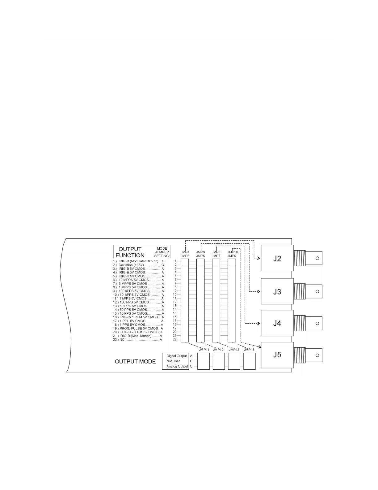
Option 03 incorporates an extremely flexible output selection system using jumpers on the Option
03 printed circuit board. Each of the four rear-panel BNC-type I/O connectors, included with
Option 03, can be configured to perform any of the available output functions. Figure 1 shows the
locations and functions for all of the jumpers on the Option 03 board.
Function Selection
Jumpers JMP3 through JMP10 determine which output function their respective I/O connectors
perform. The dotted lines in Figure 1 show the relationships between the jumper strips and the
connectors. Set the jumper for each connector to the appropriate location for the type of output
signal desired. Jumpers JMP4, 6, 8 and 10 refer to Output Function selections 1 and 2. Jumpers
JMP3, 5, 7, and 9 refer to Output Function selections 3 through 22. The signals available are listed
in the text to the left of the jumpers in Figure 1.
Mode Selection
In addition to specifying the output signal type for each individual connector, it is necessary to
define whether the signal is analog or digital. This is accomplished using jumpers JMP11, JMP12,
JMP14, and JMP15. Each of these jumpers corresponds to the output function jumper for one of
the output connectors; the relationships are illustrated by the dotted lines in Figure C.1. Table C.1
shows the Function and Mode jumper settings for all of the various output signal types. Only the
Modulated IRIG-B and Deviation outputs are analog; all others are digital.
Figure C.1: Option 03 Jumper Configuration