2 Unpacking the Clock
ADDITIONAL PARTS INSIDE
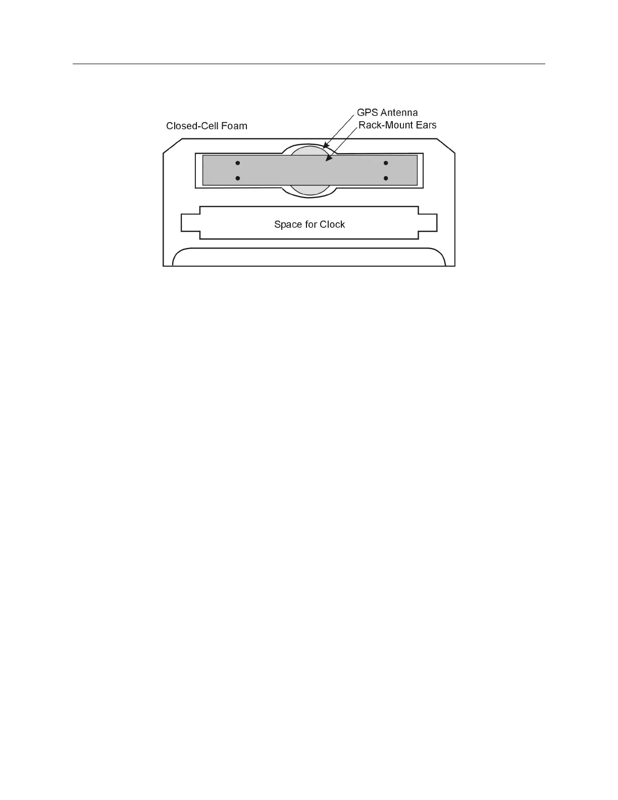
Figure 1.1: Packaging of Accessories
Antenna cable, clock and operation manual are located between the two pieces of closed-cell foam.
The rack-mount ears and antenna are embedded in the packing foam side labeled ADDITIONAL
PARTS INSIDE.
1.4 Attaching Rack-Mount Ears to 1084A/B/C Series Clocks
Each Model 1084A/B/C comes with two rack-mount ears suitable for mounting in a 19-inch system
rack. These ears have four mounting holes, two of which are used to attach them to the sides of the
clock. Since it is required to remove the M25 screws which attach the cover to the chassis, it may
be good to attach the ears after first making any jumper configuration inside the clock. You will
want to return to this section after making these changes. See Chapter 5, Setting Internal Jumpers,
for information on selecting jumpers.
1.4.1 Mounting Instructions
1. Using a Torx T25 driver or large slot screwdriver, remove the four M25 screws attaching the
clock cover to the chassis. Use either a T-25 or large slot screwdriver.
2. With the ear facing out from the front panel, match the lower set of holes of the ear to the
cover/chassis and remount the M25 screws.
3. Repeat this procedure with the other side of the chassis and other ear.