26 Setting Internal Jumpers
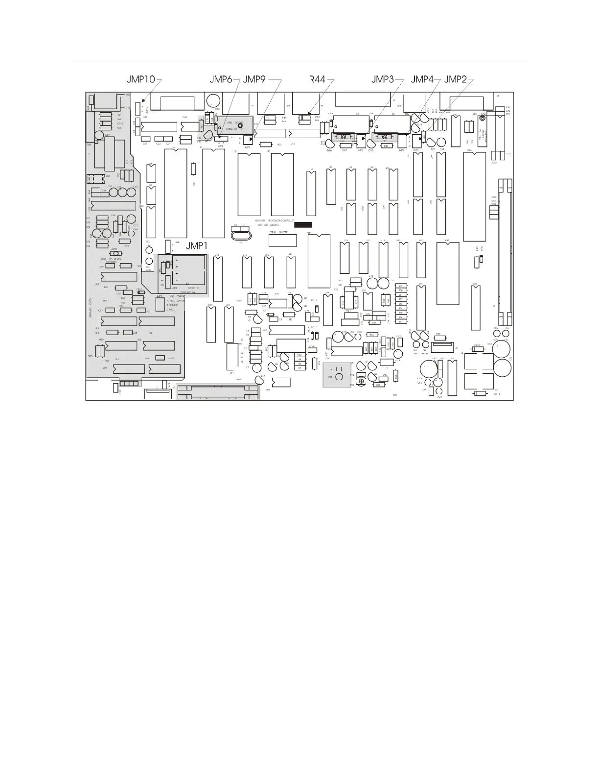
Figure 5.1: Model 1084A/B/C Main Board
(Not all components are shown. Components shown are for the purpose of locating jumpers.)
5.2.1 Output Function at P1, No Jumper
The output function at P1 is dedicated to modulated IRIG-B (analog) and cannot be changed.
There are no jumpers available to change this output to any other function.
5.2.2 JMP1, I/O Connector Used as Input
The Model 1084A/B/C can accept event data input through I/O connectors P3 and J2 (Event
A/Deviation and RS-232 respectively). To accomplish this, set jumper JMP1 to either the B or A
position, corresponding to connectors P3 and J2 respectively.
Event and Deviation Channel Configuration
To record and display the various event and deviation measurements requires re-configuring the
hardware and event settings on the Model 1084A/B/C. As illustrated in Figure 5.1, on a standard
Model 1084A/B/C there are two I/O connectors, which can also be used for an input function.
These input functions and their assigned connectors are as follows: