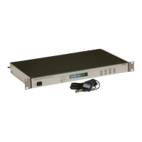
8 Front and Rear Panels
and Command Set, for a detailed description of RS-232 commands to control the front panel. The
front-panel pushbutton keys are described below.
Time
Sets the display to the Time Display Mode. There are four modes of the time display available and
repeated pressing of this key will cause the display to scroll through all four modes. Changing the
time display has no effect on the time data, which is output from rear-panel timing outputs.
Position Cycles the display through the longitude, latitude, and elevation data readouts of the
antenna location according to the most recent, or averaged, position fix.
Event/Deviation Selects Event and/or Deviation Data recorded by the specific Model clock; up
to 500 event records or updated 1-PPS deviation data. For additional details, see Event Inputs in
Chapters 5, 6, 8 and 9.
Status Toggles the display between four status display modes: Clock, Receiver, DCXO and EEP-
ROM, including the display of GPS satellite acquisition and synchronization.
Setup Invokes a series of menus used to adjust configurable parameters within the clock. In
numeric data entry mode, moves the cursor to the left.
Up Used in conjunction with the Setup menus to adjust values upward, or to scroll upward through
the available menu choices. Also assists in navigating through main Setup menus in normal order.
Down Used in conjunction with the Setup menus to adjust values downward, or to scroll downward
through available menu choices. Also assists in navigating through main Setup menus in reverse.
Enter Used for confirming changes made within Setup menus. Generally, pressing Enter also
advances to the next parameter, or returns to the previous menu level. In numeric data entry
mode, moves the cursor to the right.
2.3 Rear Panel Identification and Connectors
This section contains information to assist you in identifying where to connect inlet power, the
GPS antenna cable and all of the input and output cables on the Model 1084A/B/C series clocks.
Figure 2.2: Model 1084A/B/C Rear Panel Description
2.3.1 Power Inlet
To cover all of the possible inlet power conditions, the Model 1084A/B/C has three optional power
supplies. Please examine the paperwork you received, to make sure you have correctly identified
the inlet connection. Supply types are listed below:

 Loading...