52 Timing, IRIG-B and Pulses
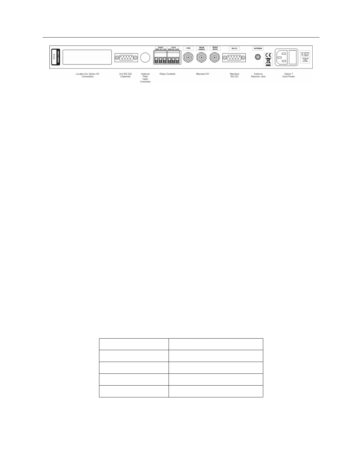
Figure 7.1: Rear Panel Descriptions
7.2.1 Standard Inputs/Outputs
All of these models have three, BNC female connectors that can supply timing signals to external
equipment. One of these connectors (P3) may also be configured for an event/deviation input.
Two of the outputs are designed for digital signals and one for analog. Signals supplied to the
digital drivers include unmodulated IRIG-B, 1 pulse per second, and programmable pulse. The
third connector is set up for a modulated IRIG-B only.
7.2.2 Digital Drivers
Each of the digital outputs is driven by a CMOS 74HC126 quad driver capable of supplying 75 mA
at 5 Vdc, which may be fanned out to a number of devices. To determine the maximum number of
devices that the digital drivers can support, you will need to determine the load current, or input
impedance, for each device. For example, if the IED timing input signal (e.g. IRIG-B003) requires
10 mA, one output channel should be able to support 7 identical devices.
7.2.3 Analog Driver
The 1084A/B/C has one analog driver available exclusively for modulated IRIG-B signals. Ad-
ditional analog drivers may be added as options (e.g. Option 03, 27, 29). The analog driver is
basically a push-pull audio design (MMBT4401/4403), which supplies a 4.5 Volt peak-to-peak (10
Vpp on Option 03) signal through a 19.6-ohm source resistor to IED’s. As the load current increases
(by adding external IED’s), more voltage is dropped across the clock source resistor and the drive
voltage decreases. Matching the modulated IRIG-B output voltage to the IED input is sometimes
critical, so it is important to match the modulated IRIG-B peak-to-peak voltage to within the
specified range of the IED. Table 7.1 shows how the actual drive voltage varies with increasing load
current. For IED’s with a restricted input range, it may be necessary to match the available drive
voltage to the IED through a small dropping resistor of adequate power rating.
Drive Current, mA Actual Drive Voltage, Vpp
0 4.5 (no load)
1 4.48
10 4.3
100 2.54
Table 7.1: Drive Current vs. Voltage